


Page 17
www.tri-m.com
TCB1000 Series User Guide Rev A
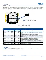
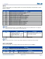
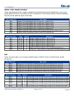
LED Port (CN9)
CN9 has the five LED Ports. The ports use the respective isolated power. Each port is independently isolated
up to 2500V, and does not require any limiting resistors, allowing you to directly connect an LED to the port.
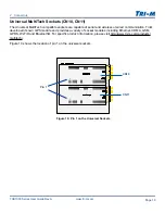
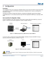
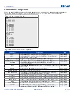
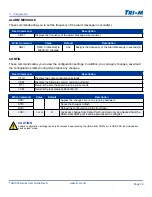
2 Connectors
Note
The LEDs are independently isolated from each other, and the LEDs will automatically be disabled if the respective
serial port is turned off. The LEDs cannot be configured.
Note
+
is the anode, and
-
is the cathode
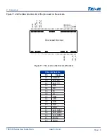
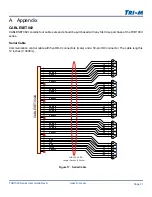
Figure 9: CN9 Connector Pinouts
CN7
CN4
CN5
CN3
CN6
CN12
CN13
CN10
CN11
CN9
CN8
A32
C19
D19
B32
5
5
1
1
- - - - -
+
+
+
+
+
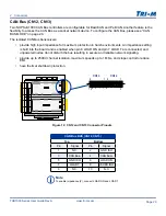
LED Port (CN9)
LED
Top
Bottom
Description
Pin
Signal
Pin
Signal
LED1
1
LED-
1
LED+
•
LED1 shows the status/activity of a network module inserted in
socket 1.
•
It is powered by the RS-232 port 1 isolated power.
LED2
2
LED-
2
LED+
•
LED2 shows the status/activity of a network module inserted in
socket 2.
•
It is powered by the RS-232 port 2 isolated power.
LED3
3
LED-
3
LED+
•
LED3 is controlled by the GPI04 pin of socket 2.
•
It is powered by the RS-232 port 3 isolated power.
LED4
4
LED-
4
LED+
•
LED4 shows if the UART is operating at high speed clock =
14.7456MHz or low speed = 1.8432MHz.
•
It is powered by the RS-232 port 4 isolated power.
LED5
5
LED-
5
LED+
•
LED5 is the CPU heart beat.
•
It is powered by the RS-485 isolated power.