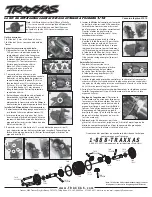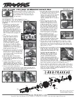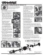
1/16th Scale Slash and E-Revo Center Differential Kit
www.TRAXXAS.com
Traxxas, 6200 Traxxas Way, McKinney, TX 75070, Phone: 972-265-8000, Fax: 972-265-8011, e-mail: [email protected]
KC1896-R00 130613
Covers Part #7014
Note:
This 1/16-scale Slash/E-Revo center differential
comes assembled with 50K differential fluid and is
tunable by changing fluid thickness. The 50K fluid is
recommended for best all-around performance.
Tools needed:
1.5mm hex wrench, 2.0mm hex wrench,
2.5mm hex wrench, Traxxas 4-way nut driver
Remove transmission from the vehicle:
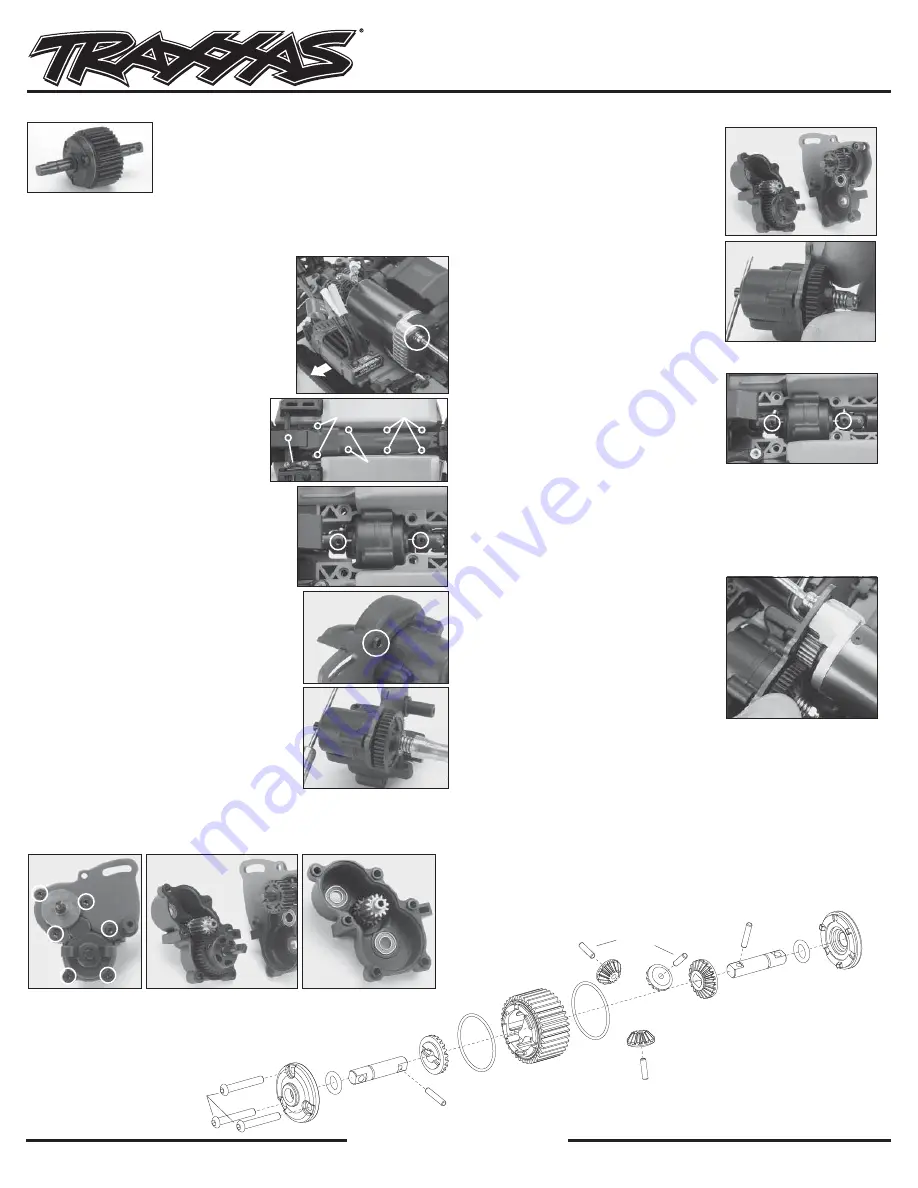
1. Disconnect the three motor wires from
the ESC; then, open the right side battery
compartment door to slide the ESC out away
from the motor. Remove the silver 3x8mm
cap head screw from the motor (A). Pull the
motor toward the rear to remove it from the
chassis.
Note:
The ESC only needs to be shifted
over far enough to remove the motor.
2. Turn the chassis upside down to access
the center skid plate. Remove the
screws from the center skid plate, as
indicated in photo B: (4) 3x8mm button
head screws, (2) 3x10mm button head
screws, (2) 3x15mm button head screws,
and (1) 3x12mm countersunk screw from the
steering bell crank. Remove the center skid
plate from the chassis.
3. Remove each screw pin from the front and
rear output yokes exiting the transmission
(C). Pull the yokes away from the transmission
to release the transmission from the top of
the chassis.
Install the differential into the transmission:
1. Remove the gear cover by removing the 2x6mm
cap head screw from the motor plate (D).
2. Insert a 1.5mm hex driver into the hole in
the input shaft and use a 4-way nut driver to
remove the spur gear and slipper spring from
the input shaft of the transmission (E).
3. Remove the (6) 2x12mm countersunk screws
from the transmission case (F); then, separate
the transmission halves to access the output
gear and shaft assembly (G). Remove the output
gear and shaft assembly (H).
4. Insert the center differential in the
transmission case half (I). Reconnect the
transmission halves together, making sure
the gears are aligned correctly. Secure
the transmission halves together with (6)
2x12mm countersunk screws.
5. Slide the spur gear onto the input shaft
along with the slipper spring (J); then,
thread the 3.0mm nylon lock nut onto
the shaft. Adjust the slipper nut to allow
the spur gear to slowly spin on the shaft
while the shaft is locked with the 1.5mm
hex wrench.
Note:
This adjustment is
approximately ¾-turn from snug (spring
collapsed).
Reinstall the transmission
1. Set the transmission back on the chassis.
Attach the center drive shaft yokes to the
output shafts. Secure the output yokes
with the (2) screw pins (K).
2. Attach the center skid plate to the
chassis; then, secure it with the same
screws.
Note:
The front end of the center skid plate must fit under the front
skid plate before securing the 3x12mm countersunk steering bell crank screw.
3. Slide the motor/motor mount assembly back onto the motor plate. Set
the gear mesh (L), and then secure the motor with the silver 3x8mm cap
head screw.
Setting gear mesh:
Loosen the motor
screw just enough to shift the motor on
the motor plate. Press the pinion gear
up against the spur gear until the gear is
hard to turn. Gently slide the pinion gear
away from the spur gear until there is just
a small amount of play between the two
gears, and then tighten the motor screw
(L).
4. Reconnect the motor wires; then, slide
the ESC back toward the motor until it stops. Close the right side battery
door; then, secure the gear cover to the motor plate with the same
2x6mm cap head screw.
A
C
B
D
E
I
J
F
G
H
If you have questions or need technical assistance, call Traxxas at
1-888-TRAXXAS
(1-888-872-9927) (U.S. residents only)
3x12mm
3x12mm
3x15mm
3x15mm
3x10mm
3x10mm
3x8mm
3x8mm
7014
2x13 BCS
7014
7014
7014X*
7014
7014X*
7014
7014X*
7014
7014X*
7014
7014X*
7014
7014X*
7014
7014
7014
7014
7014
1.5x6 PIN
7014
1.5x6 PIN
7014
1.5x8 PIN
7014
1.5x8 PIN
K
L
*
Note:
7014X is a rebuild kit that contains
the differential O-rings and gear covers.


