background image

Transition Networks 


SISTP1040-382B-LRT Install Guide 

33806 Rev. B 


https://www.transition.com


Page  1  of  39 


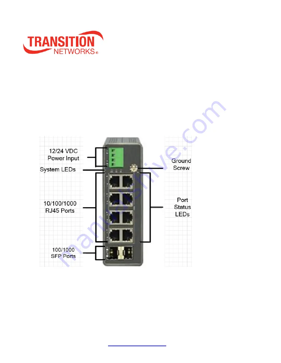
SISTP1040-382B-LRT 

Unmanaged Hardened Gigabit Ethernet PoE+ Switch with Low Voltage 

Input 

(8) 10/100/1000Base-T Ports + (2) 100/1000Base-X SFP Slots 


Install Guide 

33806 Rev. B 


Содержание SISTP1040-382B-LRT

Страница 1: ...LRT Install Guide 33806 Rev B https www transition com Page 1 of 39 SISTP1040 382B LRT Unmanaged Hardened Gigabit Ethernet PoE Switch with Low Voltage Input 8 10 100 1000Base T Ports 2 100 1000Base X...

Страница 2: ...data or damage the system or equipment SISTP1040 382B LRT Industrial Unmanaged GbE PoE Switch Install Guide 33806 Rev B Record of Revisions Rev Date Description of Changes A 11 14 19 Initial release...

Страница 3: ...2 Installing the Switch 16 Package Contents 16 Switch Mounting Options 16 Mounting the Switch on a DIN Rail 17 Mounting the Switch on Wall Optional 18 Grounding 19 Installing SFP Modules 20 Connect P...

Страница 4: ...ps www transition com Page 4 of 39 User Information 33 RoHS WEEE and Environmental Programs 33 Electrical Safety Warnings 34 Warranty 35 Five Year Limited Hardware Warranty 35 Box and Device Labels 36...

Страница 5: ...e reliable operation in temperatures between 40 C and 70 C Transition Networks hardened switches are certified to operate reliably in harsh environments such as those found on factory floors outdoor e...

Страница 6: ...ard switching architecture Switching Capacity 20 Gbps Connectors Eight 10 100 1000 Base T RJ 45 and two 100 1000 Base x SFP MAC Address 4K MAC address table Status LEDs System Power 1 Power 2 Port Sta...

Страница 7: ...5 40 to 85 10000 3000 Dimensions Weight Mounting Dimension WxHxD Weight Mounting Type Millimeter Inches Kilograms Pounds 44 x 135 x 130 1 7 x 5 3 x 5 1 0 56 1 25 DIN rail Wall Voltage and Frequency Pr...

Страница 8: ...romagnetic Compatibility Limitation of voltage fluctuation and flicker in low voltage supply systems for equipment rated up to 16A Class C EMS IEC 61000 4 2 ed1 2 2001 ESD Test level 3 8kV contact 15k...

Страница 9: ...W PoE Load Input Voltage Unit Current Unit Power Unit 12VDC 1 V 6 67 A 80 4 W DC Voltage Unit Current Unit Power Unit 1 1 V 1 34 A 1 474 W 3 3 0 75 2 475 120W PoE Load Input Voltage Unit Current Unit...

Страница 10: ...tions The front panel LEDs provide switch status checking and monitoring The three LED types are Power LEDs indicate if the switch is powered up correctly or not System LED indicates if the system is...

Страница 11: ...ription P1 Power1 Green On The switch is powered On correctly Lit Green when Power on Switch is Ready Off The switch is not receiving power from Power1 Blinking When POST is running P2 Power2 Green On...

Страница 12: ...may have been disabled via the switch user interface RJ45 Ports Left side Green On The port is enabled and supplying power to connected device Green Blinking An abnormal state such as overload status...

Страница 13: ...ivity Amber LED on 100M 10M Link Present No Activity Green blinking 1G Activity Port is sending or receiving data Amber blinking 100M 10M Activity Port is sending or receiving data POE Behavior LED of...

Страница 14: ...ansition Networks SISTP1040 382B LRT Install Guide 33806 Rev B https www transition com Page 14 of 39 Port LED Example TP Link up at 1G speed SFP Link up at 10G Speed POE Light on Link up at 100M spee...

Страница 15: ...Networks SISTP1040 382B LRT Install Guide 33806 Rev B https www transition com Page 15 of 39 Back Panel and Bottom Panel Side Panel Bottom Panel Reset Button Press the recessed Reset Button to reboot...

Страница 16: ...r possible future use One Switch One Terminal Block One Quick Start Guide One Mounting kit Note The switch is an indoor device If you need to use it to connect outdoor devices such as outdoor IP camer...

Страница 17: ...t to rear panel of the chassis Insert screws and tighten with a screwdriver to secure the kit Figure Attach DIN Rail Kit to the Switch 2 Insert the upper lip of the DIN rail into the DIN rail mounting...

Страница 18: ...1 Attach the wall mounting plates to rear panel of the chassis Insert screws and tighten with a screwdriver to secure the plates Figure Attach Wall Mounting Plates to the Switch Figure Wall Mount Plat...

Страница 19: ...he front panel grounding screw can be used for grounding Grounding and wire routing help limit the effects of noise due to electromagnetic interference EMI Run the ground connection from the ground sc...

Страница 20: ...tic port contains a Class 1 laser device When the ports are disconnected always cover them with the provided plug Exposed fiber optic ports may cause skin or eye damage 2 Remove a rubber plug from the...

Страница 21: ...for LED operation details PoE PoE Spec Comparison PoE Plus PoE provides extended support for new end devices with higher power requirements The IEEE 802 3at standard provides up to 30W of power to inc...

Страница 22: ...the wires to the terminal block before plugging power into the Switch product 1 Insert the negative positive DC wires into the P1 and or P2 and terminals respectively 2 To keep the DC wires from pull...

Страница 23: ...136 8Khrs Dimensions mm 65 5W 125 2H 100D Weight 0 79Kg Specifications 25079 Output Output Voltage 24VDC Current Rating 5 0A Power Rating 120 Watts Ripple Noise Max 80mVp p Voltage Range 24 28VDC Volt...

Страница 24: ...ity 20 95 non condensing Storage Temp 20 C 85 C Standards 25079 Safety UL508 UL60950 1 TUV EN60950 1 Vibration IEC60068 2 6 EMC Emission EN55011 EN55022 CISPR22 Class B EN61000 3 2 EN61000 3 3 EMC Imm...

Страница 25: ...SISTP1040 382B LRT Install Guide 33806 Rev B https www transition com Page 25 of 39 Adjusting Power Supply Output Voltage V ADJ V ADJ access to small Phillips screw turn clockwise to increase voltage...

Страница 26: ...Symptom Possible Cause Suggested Solution System LED is Off The switch is not receiving power 1 Check if correct power cord is connected firmly to the switch and to the DC outlet socket 2 Perform powe...

Страница 27: ...s outdoor Env B 3 PoE Source is outdoor PD is outdoor Env B Option 3 is the most challenging environment since both the PD and PSE are installed outdoors Caution The switch is an indoor device If it i...

Страница 28: ...ends only voice messages while SIP can carry all media forms not just voice messages Mixing POE and Non POE Devices You can mix POE and non POE devices on the same POE switch i e you can put PCs on th...

Страница 29: ...ads or disconnects from inline power verify all electrical connections from the switch to the PD An unreliable connection results in power interruptions and intermittent PD operation such as PD discon...

Страница 30: ...output voltage to any port It s possible the switch s Ethernet functions appear normal and only the PoE functions are disrupted or degraded or the switch may power down completely due to the AC distur...

Страница 31: ...pment Warnings indicate that there is the possibility of injury to person Cautions and Warnings appear here and may appear throughout this manual where appropriate Failure to read and understand the i...

Страница 32: ...smaller than the minimum permitted according to the manufacturer s specification usually about 65 mm or 2 5 in Warnings Warning Use of controls adjustments or the performance of procedures other than...

Страница 33: ...CTER LORSQUE LE CIRCUIT EST VIVANT OU MOINS QUE LA ZONE NE SOIT LIBRE DE CONCENTRATIONS IGNIFIABLES User Information Caution changes or modifications not expressly approved by the party responsible fo...

Страница 34: ...svoorschriften worden ge nstalleerd S curit lectrique IMPORTANT Cet quipement doit tre utilis conform ment aux instructions de s curit S hk turvallisuus T RKE T m laite on asennettava turvaohjeiden mu...

Страница 35: ...bnormal conditions of operation or handling including over voltage failures caused by use outside of the product s specified rating or normal wear and tear of mechanical components Transition Networks...

Страница 36: ...urn the product to the customer not repaired Non warranted products that are repaired by Transition Networks for a fee will carry a 180 day limited warranty All warranty claims are subject to the rest...

Страница 37: ...___________________________________________________________________ Describe any action s already taken to resolve the problem e g changing switch mode rebooting etc __________________________________...

Страница 38: ...t is available 24 hours a day US and Canada 1 800 260 1312 International 00 1 952 941 7600 Main Office tel 1 952 941 7600 toll free 1 800 526 9267 fax 952 941 2322 sales transition com techsupport tra...

Страница 39: ...tworks 10900 Red Circle Drive Minnetonka MN 55343 U S A tel 1 952 941 7600 toll free 1 800 526 9267 fax 952 941 2322 sales transition com techsupport transition com customerservice transition com Copy...

Отзывы: