background image

11

PUB. NO. 22-1802-03

Performance
Data

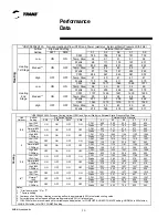
SW7

SW8

0.1

0.3

0.5

0.7

0.9

CFM

764

795

832

852

848

Temp. Rise

63

61

58

56

57

Watts

103

147

195

242

280

CFM

875

938

963

974

959

Temp. Rise

55

60

58

57

58

Watts

139

200

259

305

344

CFM

984

1029

1040

1039

980

Temp. Rise

49

47

46

46

49

Watts

185

253

304

347

357

CFM

1118

1138

1157

1125

1018

Temp. Rise

66

65

64

66

73

Watts

262

326

390

417

383

CFM

1310

1335

1277

1192

1097

Temp. Rise

57

55

58

62

68

Watts

411

498

498

472

441

CFM

1413

1399

1322

1233

1148

Temp. Rise

52

53

56

60

65

Watts

512

566

541

514

484

OFF

OFF

OFF

OFF

Heat

in

g

Heating 

1st Stage

Heating 

2nd 

Stage

OFF

OFF

ON

ON

ON

Low

High

Low

Medium**

ON

ON

High

Medium**

ON

*UD2B100AFV32A


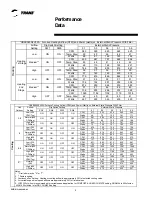
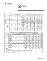
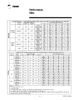
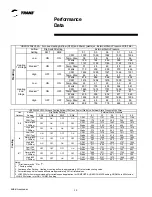
Furnace Heating Airflow (CFM) and Power (watts) vs. External Static Pressure With Filter

Airflow 

Setting

Dip Switch Setting

External Static Pressure

SW1

SW2

SW3

SW4

0.1

0.3

0.5

0.7

0.9

CFM

538

556

574

579

570

Watts

54

80

113

145

176

CFM

598

626

654

647

647

Watts

64

94

131

162

200

CFM

657

706

713

724

730

Watts

75

116

151

187

227

CFM

688

729

745

753

763

Watts

81

124

161

199

238

CFM

785

831

859

872

881

Watts

109

157

207

253

294

CFM

887

939

964

977

954

Watts

146

206

260

309

343

CFM

848

907

934

946

946

Watts

133

188

245

289

334

CFM

1018

1044

1055

1065

983

Watts

206

262

319

370

357

CFM

1139

1160

1184

1122

1020

Watts

274

344

411

417

386

CFM

1071

1089

1105

1108

1003

Watts

231

290

346

399

368

CFM

1208

1246

1249

1153

1060

Watts

323

411

469

441

410

CFM

1387

1383

1295

1221

1124

Watts

482

546

517

499

467

Notes:
1.  * First letter may be "A" or "T".
2.  ** Factory setting.
3.  Continuous Fan Setting:  Heating or cooling airflow is approximately 50% of selected cooling value.
4.  For variable speed low speed airflows are approximately 30% of listed values.
5.  LOW 350 cfm/ton is recommended for variable speed application for COMFORT & HUMID CLIMATE setting; NORMAL is 400 cfm/ton;
  HIGH 450 cfm/ton is for DRY CLIMATE setting.

Cooling

Unit 

Outdoor 

Low (350 

CFM/Ton)

Normal (400 

CFM/ton)

High (450 

CFM/ton)

Low (350 

CFM/Ton)

Airflow 

Setting

Normal (400 

CFM/ton)

High (450 

CFM/ton)

Low (350 

CFM/Ton)

Normal (400 

CFM/ton)

High (450 

CFM/ton)

OFF

OFF

OFF

Low (350 

CFM/Ton)

Normal (400 

CFM/ton)

High (450 

CFM/ton)

OFF

OFF

ON

OFF

3.0**

2.5

2

1.5

OFF

OFF

OFF

ON

OFF

OFF

OFF

ON

OFF

OFF

OFF

OFF

ON

OFF

ON

OFF

ON

OFF

OFF

ON

ON

OFF

OFF

ON

OFF

ON

ON

ON

OFF

OFF

ON

ON

*UD2B100AFV32A Furnace Cooling Airflow (CFM) and Power (Watts) vs. External Static Pressure With Filter

Dip Switch Setting

External Static Pressure

ON

ON

ON

OFF

OFF

ON

OFF

ON

ON

Содержание TUD2B060AFV32A

Страница 1: ...izontal 80 2 Stage Variable Speed Gas Fired Furnace with Whole House Air Cleaner PUB NO 22 1802 03 XV80i TUD2B060AFV32A TUD2B080AFV32A TUD2C080AFV42A TUD2B100AFV32A TUD2D120AFV52A 2009 Trane All Right...

Страница 2: ...can be converted to L P gas INTEGRATED SYSTEM CONTROL Exclusively designed operational program provides total control of furnace limit sensors blowers gas valve flame control and includes self diagnos...

Страница 3: ...pment Optional Equipment General Data TUD2B060AFV32A TUD2B080AFV32A TUD2C080AFV42A TUD2B100AFV42A TUD2D120AFV52A Performance Data Electric Data Field Wiring Diagrams Dimensions Contents 2 2 2 2 2 4 4...

Страница 4: ...gauge aluminized steel heat exchanger Multi port In shot burners Complete front service access Alternate bottom left right return air Slide out blower assembly Hingedblowerdoor Perfect fit door catch...

Страница 5: ...mostat Electronic Programmable 5 2 1 Stage Heating 1 Stage Cooling BAYSTAT340 Thermostat Heating Cooling Single Stage Mounts Vertically BAYSTAT305 Thermostat Electronic Programmable 2 Stage Heating 2...

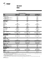
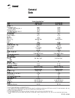
Страница 6: ...Variable SeeAirflow Table 1 2 Variable 115 1 60 Centrifugal Direct 2 1 100 2543 1727 115 1 60 0 70 0 40 Yes Whole House Air Cleaner 65 4Round Alum Steel Type 1 20 4 45 4 56 Redundant Two Stage Hot Su...

Страница 7: ...Ignition Multi port In shot 6 115 1 60 15 3 20 1 2 H x W x D 41 3 4 x 26 1 2 x 30 1 2 40 x 24 1 2 x 28 1 2 193 181 UD2B100AFV32A Upflow Horizontal 65 000 52 000 100 000 80 000 40 70 Direct 10 x 7 1 V...

Страница 8: ...137 198 259 316 361 CFM 831 883 915 935 941 Watts 122 182 238 292 345 CFM 1023 1052 1055 1061 1048 Watts 203 266 316 370 413 CFM 1156 1174 1188 1196 1085 Watts 280 351 415 482 442 CFM 1063 1094 1090...

Страница 9: ...22 1111 1101 1083 Watts 269 317 361 405 442 CFM 1310 1295 1273 1246 1136 Watts 405 457 498 535 490 CFM 1458 1420 1369 1266 1154 Watts 569 599 606 561 506 CFM 1329 1310 1287 1253 1142 Watts 424 472 516...

Страница 10: ...1334 1296 Watts 252 326 394 456 502 CFM 1167 1193 1208 1196 1193 Watts 190 255 321 378 443 CFM 1356 1378 1383 1358 1321 Watts 279 355 424 473 518 CFM 1521 1528 1537 1537 1344 Watts 379 545 534 606 55...

Страница 11: ...atts 146 206 260 309 343 CFM 848 907 934 946 946 Watts 133 188 245 289 334 CFM 1018 1044 1055 1065 983 Watts 206 262 319 370 357 CFM 1139 1160 1184 1122 1020 Watts 274 344 411 417 386 CFM 1071 1089 11...

Страница 12: ...563 640 605 CFM 1334 1376 1424 1411 1417 Watts 251 330 415 469 562 CFM 1582 1628 1659 1663 1465 Watts 387 491 595 672 595 CFM 1813 1836 1838 1707 1504 Watts 577 684 771 710 620 CFM 1704 1731 1733 1735...

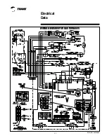
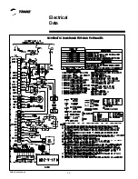
Страница 13: ...PUB NO 22 1802 03 WIRING DIAG WIRING DIAG WIRING DIAG WIRING DIAG WIRING DIAGRAMS FOR GAS FURNACES RAMS FOR GAS FURNACES RAMS FOR GAS FURNACES RAMS FOR GAS FURNACES RAMS FOR GAS FURNACES Electrical Da...

Страница 14: ...22 1802 03 SCHEMA SCHEMA SCHEMA SCHEMA SCHEMATIC DIAGRAMS FOR GAS FURNACES TIC DIAGRAMS FOR GAS FURNACES TIC DIAGRAMS FOR GAS FURNACES TIC DIAGRAMS FOR GAS FURNACES TIC DIAGRAMS FOR GAS FURNACES Elect...

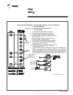
Страница 15: ...s only for thermostats requiring connection to transformer common terminal 11 Optional humidistat is to be connected between R and BK Factory installed jumper R to BK on the circuit board must be cut...

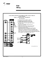
Страница 16: ...delays 9 Optional humidistat is to be connected between R and BK Factory installed jumper R to BK on the circuit board must be cut if optional humidistat is used The jumper must also be cut when apply...

Страница 17: ...ER SEE NOTE 9 FIELD ADDED JUMPER W1 TO W2 2ND STAGE WILL FIRE 10 MINUTES AFTER 1ST B C B C TO 115 V 1 PH 60 HZ POWER SUPPLY PER LOCAL CODES HUM SEE NOTE 5 FIELD WIRING DIAGRAM FOR VARIABLE SPEED 2 STA...

Страница 18: ...NOTE 9 W14 JUMPER SEE NOTE 9 From Dwg B342020 Rev 0 B C B C TO 115 V 1 PH 60 HZ POWER SUPPLY PER LOCAL CODES HUM SEE NOTE 5 FIELD WIRING DIAGRAM FOR VARIABLE SPEED 2 STAGE FURNACE 2 STAGE HEATING 1 ST...

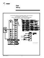
Страница 19: ...TRANSFORMER SEE NOTE 3 SEE NOTE 6 SEE NOTE 7 From Dwg B342018 Rev 0 B C B C TO 115 V 1 PH 60 HZ POWER SUPPLY PER LOCAL CODES HUM SEE NOTE 5 FIELD WIRING DIAGRAM FOR VARIABLE SPEED 2 STAGE FURNACE 2 S...

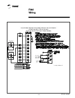
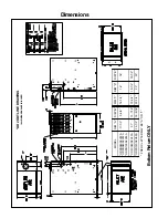
Страница 20: ...IN INCHES MODEL DIM A DIM B DIM C DIM D DIM E UD2B060AFV32A UD2B080AFV32A UD2B100AFV32A 17 1 2 9 5 8 16 1 4 16 16 UD2C080AFV42A 21 13 1 16 19 3 4 19 1 2 19 1 2 UD2D120AFV52A 24 1 2 15 5 16 23 1 4 23...

Страница 21: ...NOTES...
Страница 22: ...Since Trane has a policy of continuous product improvement it reserves the right to change design and specifications without notice Trane 6200 Troup Highway Tyler TX 75707 www trane com...

Отзывы: