Maintenance
74
RTAF-SVX001K-EN
Important:
Do not operate the unit with the sight glass
service valves opened. Close the valves
while running before and after checking the
oil level. Oil system function may be
affected and level reading will not be
accurate during operation if valves are
opened during operation.
4. Attach a 3/8” or 1/2” hose with a sightglass in the
middle to the oil sump service valve (3/8” flare) and the
oil separator service valve (3/8” flare). See
for valve locations.
Note:
Using high pressure rated clear hose with
appropriate fittings can help speed up the process.
Hose must be rated to withstand system pressures
as found on unit nameplate.
5. After the unit is off line for 30 minutes, move the
sightglass along the side of the oil sump.
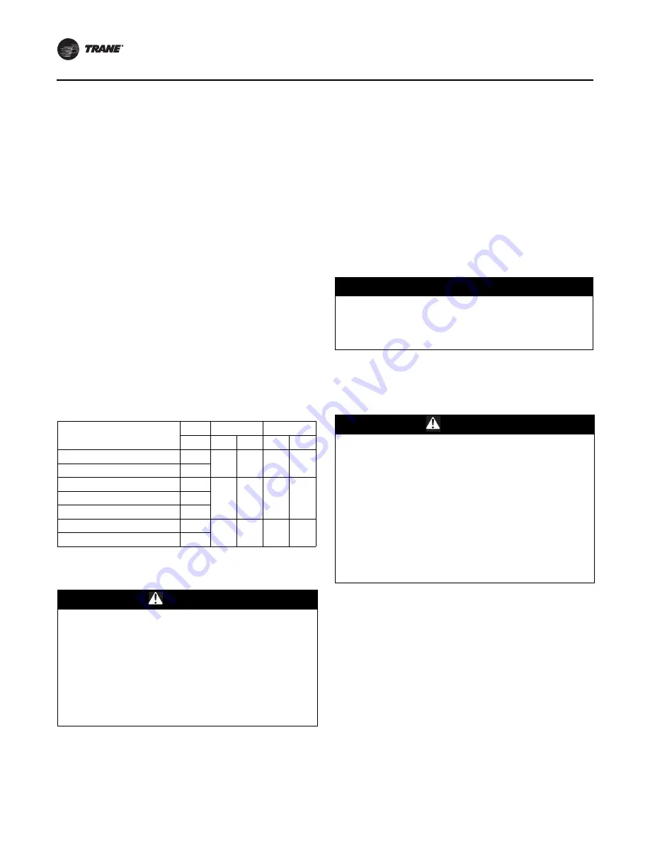
6. The nominal oil level from the bottom of the oil
separator should be approximately within the range
shown in the table below. Depending on running
conditions and the time the oil heater has been on,
some deviation from nominal levels is expected.
Important:
If level is outside range shown in table
below, contact your local Trane office.
Travel Restraint
This unit is built with travel restraint slots located on unit
top that must be used during servicing.
Microchannel Condenser Coils
For proper operation, microchannel condenser coils must
be cleaned regularly. Eliminate pollution and other
residual material help to extend the life of the coils and the
unit.
Regular coil maintenance, including annual cleaning,
enhances the unit’s operating efficiency by minimizing
compressor head pressure and amperage draw. The
condenser coil should be cleaned at minimum once each
year, or more if the unit is located in a “dirty” or corrosive
environment.
Coil Cleaning
Cleaning with cleansers or detergents is strongly
discouraged due to the all-aluminum construction. Water
should prove sufficient. Any breach in the tubes can result
in refrigerant leaks.
1. Disconnect Power to the unit.
2. Use a soft brush or vacuum to remove base debris or
surface loaded fibers from both sides of the coil.
Note:
When possible, clean the coil from the opposite
direction of normal air flow (inside of unit out) to
push debris out.
3. Using a sprayer and water ONLY, clean the coil
following the guidelines below.
a. Sprayer nozzle pressure should not exceed 580 psi.
b. The maximum source angle should not exceed 25°
to the face of the coil. See figure below. For best
results spray the microchannel perpendicular to
face of the coil.
c. Spray nozzle should be approximately 1”- 3” from
the coil surface.
Table 29. Nominal oil levels
Unit Sizes
Minimum
Maximum
Ckt
in
mm
in
mm
115, 130, 150, 170, 180
1, 2
2
50
4.5
115
200
2
200
1
2
50
5.5
140
215, 230, 250, 270
1, 2
280, 310, 350, 390
2
280, 310, 350, 390
1
2
50
6
150
410, 450, 500, 520
1, 2
WARNING
Falling Off Equipment!
Failure to follow instructions below could result in death
or serious injury.
This unit is built with fall restraint slots located on unit
top that MUST be used during servicing. These slots are
to be used with fall restraint equipment that will not
allow an individual to reach the unit edge. However
such equipment will NOT prevent falling to the ground,
as they are NOT designed to withstand the force of a
falling individual.
NOTICE:
Coil Damage!
Use of detergents could cause damage to coils.
Do not use detergents to clean coils. Use clean water
only.
WARNING
Hazardous Voltage w/Capacitors!
Failure to disconnect power and discharge capacitors
before servicing could result in death or serious injury.
Disconnect all electric power, including remote
disconnects and discharge all motor start/run
capacitors before servicing. Follow proper lockout/
tagout procedures to ensure the power cannot be
inadvertently energized. For variable frequency drives or
other energy storing components provided by Trane or
others, refer to the appropriate manufacturer’s literature
for allowable waiting periods for discharge of
capacitors. Verify with a CAT III or IV voltmeter rated per
NFPA 70E that all capacitors have discharged.


