64
RT-SVX36G-EN
Installation
6. Install a 1/2” 15 degree swing-check vacuum breaker at the top of the return coil header using
the tapped pipe connection. Position the vacuum breaker as close to the coil as possible.
Note:
Vacuum breakers should have extended lines from the vent ports to the atmosphere or
connect each vent line to the return pipe on the discharge side of the steam traps.
7.
Install a “Gate” type valve in the supply branch line as close as possible to the steam main and
upstream of any other device.
8. Install a “Gate” type valve in the return branch line as close as possible to the condensate return
main and downstream of any other device.
9. Install a strainer as close as possible to the inlet of the control valve and steam trap(s).
10. Steam trap selection should be based on the maximum possible condensate flow and the
recommended load factors.
11. Install a Float-and-Thermostatic (FT) type trap to maintain proper flow. They provide gravity
drains and continuous discharge operation. FT type traps are required if the system includes
either;
a. an atmospheric pressure/gravity condensate return;
or,
b. a potentially low pressure steam supply.
12. Position the outlet or discharge port of the steam trap at least 12" below the outlet connection
on the coil(s). This will provide adequate hydrostatic head pressure to overcome the trap losses
and assure complete condensate removal.
40 through 130 Ton units
Utilizes two steam coils stacked together. These two coils must be piped in a parallel arrangement.
The steps listed below should be used in addition to the previous steps.
illustrates the
recommended piping configuration for the steam coils.
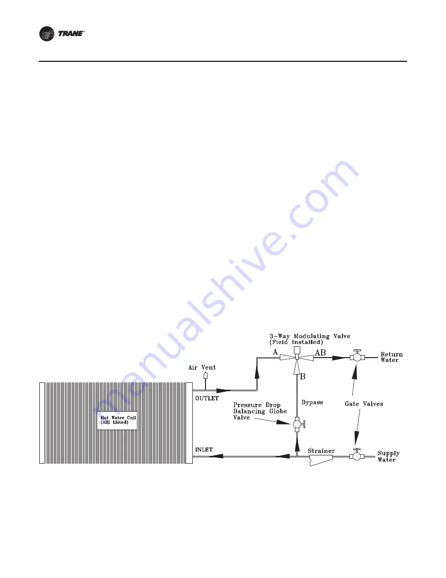
Figure 29. Hot Water Piping (20 - 75 Ton)
Содержание IntelliPak SAHL Series
Страница 47: ...RT SVX36G EN 47 Installation Figure 16 Unit rigging Figure 17 Typical unit base and roof curb cross section...
Страница 65: ...RT SVX36G EN 65 Installation Figure 30 Hot Water Piping 90 130 Ton Figure 31 Steam Coil Piping 20 36 Ton...
Страница 86: ...86 RT SVX36G EN Installation Figure 38 Field connection diagram notes for 20 89 ton CV or VAV applications...
Страница 87: ...RT SVX36G EN 87 Installation Figure 39 Typical field wiring diagram for 20 89 ton VAV control option 2307 9177...
Страница 88: ...88 RT SVX36G EN Installation Figure 40 Typical field wiring diagram for 20 89 ton VAV control option...
Страница 173: ...RT SVX36G EN 173 Startup Checklists Figure 88 Dry bulb changeover map...
Страница 175: ...RT SVX36G EN 175 Maintenance Figure 89 Unit internal fuse replacement data for air handling units...


