CG-SVX17D-EN
81
Installation - Electrical
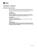
NOTICE:
Heat Tape!
Control panel main processor does not check for loss of power to the heat tape nor does it verify
thermostat operation. A qualified technician must verify power to the heat tape and confirm
operation of the heat tape thermostat to avoid catastrophic damage to the evaporator or partial
heat recovery heat exchanger.
Heater Power Supply
The evaporator shell is insulated from ambient air and protected from freezing temperatures by a
thermostatically-controlled immersion heater and strip heaters on the piping. When ever the
ambient temperature drops to approximately 37°F (2.8°C) the thermostat energizes the heaters.
The heaters will provide protection from ambient temperatures down to -20°F (-29°C).
It is required to provide an independent power source (115V 60-Hz-20 amp, 50Hz-15 amp), with a
fused-disconnect to the heaters. The heaters are factory-wired back to the unit control panel.
Note:
If evaporator is drained, the heater must be turned off in order to avoid damaging the
evaporator. The heater should only be on when the evaporator has water in it.
Partial Heat Recovery Power Supply
The partial heat recover heat exchanger is insulated from ambient air and protected from freezing
temperatures by an immersion heater. When the ambient air temperature drops to approximately
37°F (2.8°C) the thermostat energizes the heaters. The heaters will provide protection from ambient
temperatures down to -20°F (-29°C).
It is required to provide an independent power source (115V 60-Hz-20 amp, 50Hz-15 amp), with a
fused-disconnect to the heater. The heaters are factory-wired back to the unit control panel.
Note:
If partial heat recovery heat exchanger is drained, the heater must be turned off in order to
avoid damaging the partial heat recovery heat exchanger. The heater should only be on
when the heat recovery heat exchanger has water in it.
Water Pump Power Supply
Provide power supply wiring with disconnect for the chilled water pump(s).
Interconnecting Wiring
Chilled Water Flow (Pump) Interlock
All CGAM model chillers have a factory-installed flow switch. In addition, it is recommended to use
an additional field-supplied control voltage contact input through an auxiliary contact to prove
flow. Connect the auxiliary contact to 1X5-3 and 1X5-9. Refer to the field wiring for details. The
auxiliary contact can be a BAS signal, starter contactor auxiliary or any signal which indicates the
pump is running.
Chilled Water Pump Control
An evaporator water pump output relay closes when the chiller is given a signal to go into the Auto
mode of operation from any source. The contact is opened to turn off the pump in the event of most
machine level diagnostics to prevent the build up of pump heat.
The relay output from 1A9 is required to operate the Evaporator Water Pump (EWP) contactor.
Contacts should be compatible with 115/240 VAC control circuit. Normally, the EWP relay follows
the AUTO mode of the chiller. Whenever the chiller has no diagnostics and is in the AUTO mode,
regardless of where the auto command is coming from, the normally open relay is energized. When
the chiller exits the AUTO mode, the relay is timed to open in an adjustable (using TechView) 0 to
30 minutes. The non-AUTO modes in which the pump is stopped, include Reset, Stop, External
Содержание CGAM
Страница 44: ...44 CG SVX17D EN Installation Mechanical Figure 39 CGAM W 80 120 Ton Rigging X Z Y ...
Страница 101: ...CG SVX17D EN 101 CGAM Operating Principles Figure 76 Pressure Enthalpy Curve Pressure Enthalpy Liquid Gas 1 2 3 4 5 ...
Страница 104: ...104 CG SVX17D EN CGAM Operating Principles Figure 79 10 15 Ton Compressor Internal Components ...
Страница 105: ...CG SVX17D EN 105 CGAM Operating Principles Figure 80 15 30 Ton Compressor Internal Components ...
Страница 135: ...CG SVX17D EN 135 Controls Interface Figure 87 Diagnostic View ...
Страница 149: ...CG SVX17D EN 149 Unit Start Up Procedures Figure 95 Power Up to Starting ...
Страница 185: ...CG SVX17D EN 185 Unit Wiring S2075 1 20 35 Ton Slant Frame Table of Contents ...
Страница 186: ...186 CG SVX17D EN Unit Wiring S2075 2 20 35 Ton Slant Frame Legend ...
Страница 187: ...CG SVX17D EN 187 Unit Wiring 20 35 Ton Slant Frame Legend ...
Страница 188: ...188 CG SVX17D EN Unit Wiring S2075 3 20 35 Ton Slant Frame Notes ...
Страница 189: ...CG SVX17D EN 189 Unit Wiring 20 35 Ton Slant Frame Notes ...
Страница 190: ...190 CG SVX17D EN Unit Wiring S2075 4 20 35 Ton Slant Frame Compressor Power Circuit 1 ...
Страница 191: ...CG SVX17D EN 191 Unit Wiring 20 35 Ton Slant Frame Compressor Power Circuit 1 ...
Страница 192: ...192 CG SVX17D EN Unit Wiring S2075 6 20 35 Ton Slant Frame Fan Power Circuit 1 ...
Страница 193: ...CG SVX17D EN 193 Unit Wiring 20 35 Ton Slant Frame Fan Power Circuit 1 ...
Страница 194: ...194 CG SVX17D EN Unit Wiring S2075 8 20 35 Ton Slant Frame Pump Power Control ...
Страница 195: ...CG SVX17D EN 195 Unit Wiring 20 35 Ton Slant Frame Pump Power Control ...
Страница 196: ...196 CG SVX17D EN Unit Wiring S2075 9 20 35 Ton Slant Frame Compressor Control ...
Страница 197: ...CG SVX17D EN 197 Unit Wiring 20 35 Ton Slant Frame Compressor Control ...
Страница 198: ...198 CG SVX17D EN Unit Wiring S2075 10 20 35 Ton Slant Frame Fan Control 2 3 Fan Units ...
Страница 199: ...CG SVX17D EN 199 Unit Wiring 20 35 Ton Slant Frame Fan Control 2 3 Fan Units ...
Страница 200: ...200 CG SVX17D EN Unit Wiring S2075 12 20 35 Ton Slant Frame Common Control ...
Страница 201: ...CG SVX17D EN 201 Unit Wiring 20 35 Ton Slant Frame Common Control ...
Страница 202: ...202 CG SVX17D EN Unit Wiring S2075 13 20 35 Ton Slant Frame Common Control ...
Страница 203: ...CG SVX17D EN 203 Unit Wiring 20 35 Ton Slant Frame Common Control ...
Страница 204: ...204 CG SVX17D EN Unit Wiring S2075 14 20 35 Ton Slant Frame Freeze Protection ...
Страница 205: ...CG SVX17D EN 205 Unit Wiring 20 35 Ton Slant Frame Freeze Protection ...
Страница 206: ...206 CG SVX17D EN Unit Wiring V2075 1 40 70 Ton V Frame Table of Contents ...
Страница 207: ...CG SVX17D EN 207 Unit Wiring 40 70 Ton V Frame Table of Contents ...
Страница 208: ...208 CG SVX17D EN Unit Wiring V2075 2 40 70 Ton V Frame Legend ...
Страница 209: ...CG SVX17D EN 209 Unit Wiring 40 70 Ton V Frame Legend ...
Страница 210: ...210 CG SVX17D EN Unit Wiring V2075 3 40 70 Ton V Frame Notes ...
Страница 211: ...CG SVX17D EN 211 Unit Wiring 40 70 Ton V Frame Notes ...
Страница 212: ...212 CG SVX17D EN Unit Wiring V2075 4 40 70 Ton V Frame Compressor Power Circuit 1 ...
Страница 213: ...CG SVX17D EN 213 Unit Wiring 40 70 Ton V Frame Compressor Power Circuit 1 ...
Страница 214: ...214 CG SVX17D EN Unit Wiring V2075 5 40 70 Ton V Frame Compressor Power Circuit 2 ...
Страница 215: ...CG SVX17D EN 215 Unit Wiring 40 70 Ton V Frame Compressor Power Circuit 2 ...
Страница 216: ...216 CG SVX17D EN Unit Wiring V2075 6 40 70 Ton V Frame Fan Power Circuit 1 ...
Страница 217: ...CG SVX17D EN 217 Unit Wiring 40 70 Ton V Frame Fan Power Circuit 1 ...
Страница 218: ...218 CG SVX17D EN Unit Wiring V2075 7 40 70 Ton V Frame Fan Power Circuit 2 ...
Страница 219: ...CG SVX17D EN 219 Unit Wiring 40 70 Ton V Frame Fan Power Circuit 2 ...
Страница 220: ...220 CG SVX17D EN Unit Wiring V2075 8 40 70 Ton V Frame Pump Power Control ...
Страница 221: ...CG SVX17D EN 221 Unit Wiring 40 70 Ton V Frame Pump Power Control ...
Страница 222: ...222 CG SVX17D EN Unit Wiring V2075 9 40 70 Ton V Frame Compressor Control ...
Страница 223: ...CG SVX17D EN 223 Unit Wiring 40 70 Ton V Frame Compressor Control ...
Страница 224: ...224 CG SVX17D EN Unit Wiring V2075 10 40 70 Ton V Frame Fan Control 2 3 Fan Units ...
Страница 225: ...CG SVX17D EN 225 Unit Wiring 40 70 Ton V Frame Fan Control 2 3 Fan Units ...
Страница 226: ...226 CG SVX17D EN Unit Wiring V2075 12 40 70 Ton V Frame Common Control ...
Страница 227: ...CG SVX17D EN 227 Unit Wiring 40 70 Ton V Frame Common Control ...
Страница 228: ...228 CG SVX17D EN Unit Wiring V2075 13 40 70 Ton V Frame Common Control ...
Страница 229: ...CG SVX17D EN 229 Unit Wiring 40 70 Ton V Frame Common Control ...
Страница 230: ...230 CG SVX17D EN Unit Wiring V2075 14 40 70 Ton V Frame Freeze Protection ...
Страница 231: ...CG SVX17D EN 231 Unit Wiring 40 70 Ton V Frame Freeze Protection ...
Страница 232: ...232 CG SVX17D EN Unit Wiring W2075 1 80 130 Ton W Frame Table of Contents ...
Страница 233: ...CG SVX17D EN 233 Unit Wiring 80 130 Ton W Frame Table of Contents ...
Страница 234: ...234 CG SVX17D EN Unit Wiring W2075 2 80 130 Ton W Frame Legend ...
Страница 235: ...CG SVX17D EN 235 Unit Wiring 80 130 Ton W Frame Legend ...
Страница 236: ...236 CG SVX17D EN Unit Wiring W2075 3 80 130 Ton W Frame Notes ...
Страница 237: ...CG SVX17D EN 237 Unit Wiring 80 130 Ton W Frame Notes ...
Страница 238: ...238 CG SVX17D EN Unit Wiring W2075 4 80 130 Ton W Frame Compressor Power Circuit 1 ...
Страница 239: ...CG SVX17D EN 239 Unit Wiring 80 130 Ton W Frame Compressor Power Circuit 1 ...
Страница 240: ...240 CG SVX17D EN Unit Wiring W2075 5 80 130 Ton W Frame Compressor Power Circuit 2 ...
Страница 241: ...CG SVX17D EN 241 Unit Wiring 80 130 Ton W Frame Compressor Power Circuit 2 ...
Страница 242: ...242 CG SVX17D EN Unit Wiring W2075 6 80 130 Ton W Frame Fan Power Circuit 1 ...
Страница 243: ...CG SVX17D EN 243 Unit Wiring 80 130 Ton W Frame Fan Power Circuit 1 ...
Страница 244: ...244 CG SVX17D EN Unit Wiring W2075 7 80 130 Ton W Frame Fan Power Circuit 2 ...
Страница 245: ...CG SVX17D EN 245 Unit Wiring 80 130 Ton W Frame Fan Power Circuit 2 ...
Страница 246: ...246 CG SVX17D EN Unit Wiring W2075 8 80 130 Ton W Frame Pump Power Control ...
Страница 247: ...CG SVX17D EN 247 Unit Wiring 80 130 Ton W Frame Pump Power Control ...
Страница 248: ...248 CG SVX17D EN Unit Wiring W2075 9 80 130 Ton W Frame Compressor Control ...
Страница 249: ...CG SVX17D EN 249 Unit Wiring 80 130 Ton W Frame Compressor Control ...
Страница 250: ...250 CG SVX17D EN Unit Wiring W2075 10 80 130 Ton W Frame Fan Control 2 3 Fan Units ...
Страница 251: ...CG SVX17D EN 251 Unit Wiring 80 130 Ton W Frame Fan Control 2 3 Fan Units ...
Страница 252: ...252 CG SVX17D EN Unit Wiring W2075 11 80 130 Ton W Frame Fan Control 4 5 Fan Units ...
Страница 253: ...CG SVX17D EN 253 Unit Wiring 80 130 Ton W Frame Fan Control 4 5 Fan Units ...
Страница 254: ...254 CG SVX17D EN Unit Wiring W2075 12 80 130 Ton W Frame Common Control ...
Страница 255: ...CG SVX17D EN 255 Unit Wiring 80 130 Ton W Frame Common Control ...
Страница 256: ...256 CG SVX17D EN Unit Wiring W2075 13 80 130 Ton W Frame Common Control ...
Страница 257: ...CG SVX17D EN 257 Unit Wiring 80 130 Ton W Frame Freeze Protection ...
Страница 258: ...258 CG SVX17D EN Unit Wiring W2075 14 80 130 Ton W Frame Freeze Protection ...
Страница 259: ...CG SVX17D EN 259 Unit Wiring 80 130 Ton W Frame Common Control ...
Страница 260: ...260 CG SVX17D EN Unit Wiring 2076 1 Field Wiring Diagram ...
Страница 261: ...CG SVX17D EN 261 Unit Wiring C TRANE Field Wiring Diagram ...
Страница 262: ...262 CG SVX17D EN Unit Wiring 2076 2 FUSE Field Wiring Diagram Notes ...


