5.1.2 Standard connections and connection components
Base frame connection
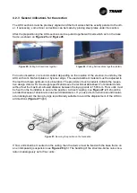
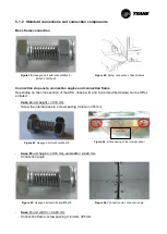
Figure 39:
Hexagon bolt with locknut M8x20 /
M10x30 / M12x40
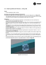
Figure 40:
Screw connection of base frames
Connection via panels, connection angles and connection frame
Depending on the cross section of the AHU, cases A, B and C (as described below) can be differ-
entiated.
-
Case A:
unit height <= 610 mm
Screw the internal panels, screw spacing minimum 305 mm
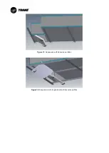
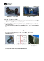
Figure 41:
Hexagon bolt with nut M6x16
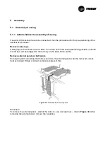
Figure 42:
Hole spacing of the internal panel
-
Case B:
unit height >= 915 mm, unit width < 2.440 mm
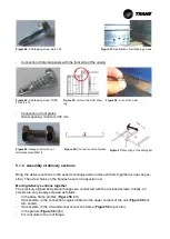
Connection angle
Figure 43:
Hexagon bolt with locknut M8x20
Figure 44:
Connection via connection angle
-
Case C:
unit width >= 2.440 mm
Connection frame, screw spacing minimum 305 mm
n x 305


