


A801X-SVX001-1A-EN
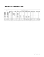
15
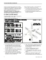
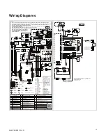
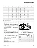
Wiring Diagrams
BK BLACK
WH WHITE
YL YELLOW
OR ORANGE
GR GREEN
BR BROWN
RD RED
BL BLUE
YL/44
YL/43
WH/40
WH/40
BK/WH/38
YL/46
YL/5
2
WH/17
WH/17
WH/21
WH/21
BK/22
BK/22
WH/20
BK/18
BL/2
BL/2
BL/5
BL/5
RD/6
RD/6
RD/9
RD/9
8/
R
G
WH/12
YL/50
YL/50
YL/49
YL/49
G
R
/YL/31
13/
L
Y/
R
G
YL/51
YL/51
YL/48
YL/48
BK
/29
BK/29
OR/11
O
R
/11
YL/47
74/
L
Y
BOX HARN
TO BURNER
BURNER BOX
GND
NOTES:
1. IF ANY OF THE ORIGINAL WIRING SUPPLIED WITH THIS FURNACE MUST BE REPLACED, IT MUST BE WITH WIRE
HAVING A TEMPERATURE RATING OF AT LEAST 105°C. WIRES 12, 18, 20, 48, 49, 50, 51, 92 & 93 MUST BE RATED TO 250°C.
2. FOR PROPER AIRFLOW IN COOLING/HEAT PUMP MODE, "Y1" ON THE THERMOSTAT MUST BE CONNECTED TO "Y1"
OF THE IFC. SEE INSTALLER'S GUIDE FOR FIELD WIRING.
3. THE INDOOR BLOWER MOTOR AIRFLOW TABLES ARE LOCATED IN THE SERVICE FACTS. TO CHANGE AIRFLOW USE
THE MENU/OPTIONS BUTTONS.
4. LINE CHOKE AND WIRE BK/28 ONLY USED ON MODELS WITH 1 HP MOTORS.
5. FLAME SENSE TEST PADS: 1 VDC = 1 MICROAMP. FLAME CURRENT CAN VARY DEPENDING ON THE VOM THAT IS USED
AND THE VOLTAGE SUPPLIED TO THE FURNACE.
THE ACCEPTABLE RANGE IS 0.75-3 MICROAMPS.
6. IF APPLICABLE CONNECTION FOR FACTORY
SEE NOTE 2
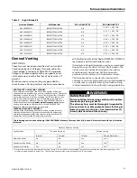
ELECTRICAL RATING
INPUT: 24VAC, 60 HZ.
TNS SEC. CURRENT: 450MA.
+ MV LOAD
MV OUTPUT: 1.5A @ 24 VAC
IND OUTPUT: 2.2 FLA, 3.5 LRA
@120 VAC
IGN OUTPUT: 2.0 A @ 120 VAC
CIRC. BLOWER OUTPUT:
14.5 FLA, 25 LRA @ 120 VAC
HUMIDIFIER & AIR CLEANER
(DRY CONTACTS)
MAX. LOAD: 1.0A @ 120VAC
24 VAC OR 120 VAC MAY BE
USED
FUSE: 5A
INTEGRATED FURNACE CONTROL
LINE
24 V
LINE
24 V
FIELD
WIRING
FACTORY
WIRING
RAF REVERSE
AIR FLOW
PS PRESSURE
SWITCH
FRS FLAME ROLLOUT
SWITCH
FP FLAME PROBE
IGN HOT SURFACE
IGNITER
** INTERNAL THERMAL PROTECTION
FUSE
GROUND
SEE NOTE 5
PANEL LOOP
H LINE
N NEUTRAL
GND GROUND
HLO HIGH LIMIT
OUTPUT
HLI HIGH LIMIT
INPUT
PS PRESSURE SWITCH
INPUT
IND INDUCER
IFC INTEGRATED
FURNACE
CONTROL
RAF REVERSE
AIR FLOW
TH 24VAC (HOT)
TR 24VAC (COMMON)
MVC MAIN VALVE
COMMON
MV MAIN VALVE
TNS TRANSFORMER
ILI INDUCER LIMIT
INPUT
IGN IGNITER
FP FLAME PROBE
YL/45
YL/45
WH/15
WH/15
W
H/16
WH
/16
YL/3
YL/3
BK/39
BK/39
YL/WH/36
BL/WH/37
BK
/14
BK/14
BK/13
BK/13
BK/WH/26
BK/WH/26
BL/WH/25
BL/WH/25
YL/WH/24
YL/WH/24
RD
/W
H/23
RD/WH/23
RD/WH/35
BK/28
B
K/28
BL/57
BL/57
OR/WH/56
O
R
/WH/56
OR/WH/55
BL/42
BL/42
BK/30
BK/27
SEE
NOTE 4
LC LINE CHOKE
YL/46
YL/52
TIMINGS
PREPURGE: 0 SEC.
INTERPURGE: 60 SEC.
POST PURGE: 5 SEC.
IGN WARMUP: 20 SEC.
IAP: 3; TFI: 5 SEC.
RETRIES: 2 RECYCLES: 10
HEAT ON DELAY: UP TO 30 SEC.
COOL ON DELAY: 0 SEC.
AUTO RESTART: 60 MIN.
AUTO RESTART PURGE: 60 SEC.
1 Stage Inducer with CTM Blower Motor
D346340P01 REV H
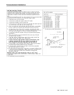
HOd
Heat Off Delay (sec)
IdL
Idle
COF
Blower Tap for Continuous Fan
Ht
Heating
COP C1
.
Blower Tap for Compressor Mode
E04
tP
Blower Tap Number
COF
Continuous Fan
E05
CP1
Cooling/Heat Pump Mode
dft
Defrost Mode
HtP H1
.
Blower Tap for Heating Mode
rUn
Orn
Orientation
Err
Active Alarm Menu
E01
L6F
Last 6 Faults (To Clear,
Hold Option Button 5 sec)
E08
Flame current is low, but still
strong enough to allow operation
Cr
Code Release Number
E11
(1) Gas valve not energized
(2) Gas valve relay stuck closed
COd
Cooling Off Delay (sec)
E12
Open fuse
Open Pressure Switch
(1) Igniter relay fails
(2) Igniter open
Status Codes
Menu Options
Open Thermal Limit, Rollout Switch,
or Reverse Airflow Switch
Shorted Pressure Switch
Flame detected, should not be present
Voltage reversed polarity
Bad Grounding
Error Codes
Run Test Mode
Recycles exceeded (loss of
established flame or PS open x10)
Gas Valve not energized when it
should be exceeded after 10 times
Loss of IRQ or internal failures
Retry exceeded (Failed to est flame)
Gas valve is energized whenit should be off
WH/83
WH/83
BK/WH/84
BK/85
BK/85
YL/WH/86
BL/WH/87
RD/WH/88
OR/WH/89
BL/90
BL/90
GR/BK/91
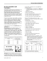
ALTERNATE WIRING DIAGRAM - BLOWER MOTOR
BK/92
WH/93
BUTT SPLICE-WITH HEAT SHRINK
BUTT SPLICE-WITH HEAT SHRINK
85/
L
B
SEE NOTE 6
59/
L
Y
YL/95
YL/96
YL/96
ALTERNATE
X
X
24v
120v
TNS
VENT
MOTOR
(INDUCER)
**
GAS
VALVE
MV C
RAF-1
IGN
PS
X
THERMAL_LIMIT
FLAME_ROLLOUT2
FLAME_ROLLOUT1
FLAME_PROBE
FP
HLI
MV
GND
TH
MVC
HLO
PS
TR
ILI (NOT USED)
IGN-N
IND-N
IND-H
IGN-H
IFC
LINE
NEUTRAL
W R G B/C Y/Y1
THERMOSTAT
FP
MENU OPTION
TAP1
TAP2
TAP3
TAP4
TAP5
GND
LINE-N
CIRC-N
(bloc
k
e
d)
TNS-N
TNS-H
CIRC-H
LINE-H
3
2
1
4
3
1
2
1
2
2
1
1
2
JUNCTION BOX
120v 60 Hz. 1 PH
POWER SUPPLY PER LOCAL CODE
H
N
GND
X
RAF-2
10
9
8
7
6
5
4
3
2
1
1
2
3
4
12
11
10
9
8
7
6
5
4
3
2
1
1
2
3
4
5
6
7
8
9
10
11
12
6
5
4
3
2
1
1
2
3
1
2
3
4
1
2
2
1
1
2
3
LINE CHOKE
REGAL -ENSITE
BLOWER
MOTOR
N
G
L
COM
®
1
2
3
4
5
6
1
2
3
12
11
10
9
8
7
6
5
4
3
2
1
1
2
3
4
5
1
2
3
4
BLOWER
MOTOR
C
L
G
N
S1
1
2
S2
1
2
E2
.
1
E2
.
2
E2
.
3
E3
.
1
E3
.
2
E6
.
1
E6
.
2
E6
.
3
E7
.
1
BLOWER
HOUSING
GND
BLOWER
HOUSING
GND
SEE NOTE 1
SEE NOTE 1
PROGRAMMING ONLY.
A801X
BL
BL
RD
RD
YL
YL
YL
BK
WH
GR/YL
GR/YL
YL
GR
YL
YL
YL
BK
BK
WH
WH
BK
BK
BK
BK
BL
RD
BK
BK
WH
WH
YL
YL
OR
OR
BURNER
BOX GND
BK
PANEL LOOP
YL
WH
WH
WH
RD/WH
RD/WH
BL/WH
BL/WH
BK/WH
BK/WH
BK
BK
BL
BL
OR/WH
OR/WH
YL/WH
YL/WH
BK
BK
WH
WH
DEFAULT BLOWER MOTOR TAP SELECTIONS
COF (CONSTANT FAN): TAP 1
COP (COOLING / HP): TAP 7
HT ( GAS HEAT): TAP 5
®
VENT
MOTOR
(INDUCER)
**
1
2
3
IGN
ILI
TR
PS
HLO
MVC
TH
GND
MV
HLI
FP
W R
G B/C Y/Y1
THERMOSTAT
LINE-H
CIRC-H
TNS-H
TNS-N
CIRC-N
LINE-N
IGN-H
IND-H
IND-N
IGN-N
1
2
3
4
5
6
7
8
9
10
1
2
3
4
4
3
1
3
2
1
IFC
TAP1
TAP2
TAP3
TAP4
TAP5
GND
1
2
3
4
5
6
JUNCTION BOX
120v 60 Hz. 1 PH
POWER SUPPLY PER LOCAL CODE
H
N
GND
24v
120v
TNS
GAS
VALVE
MV
C
FLAME_ROLLOUT1
FLAME_ROLLOUT2
RAF-1
THERMAL_LIMIT
REGAL
ENSITE
--------
BLOWER
MOTOR
N
4
3
2
1
G
L
5
COM
PS
FLAME PROBE
1
2
RAF-2
2
1
LINE CHOKE
ALTERNATE
-------
BLOWER
MOTOR
G
N
4
3
2
1
L
C
5
TO: IFC CIRC-N-3 WH
TO: LINE CHOKE BK
TO: IFC GND-6 BL
TO: IFC TAP1-1 RD/WH
TO: IFC TAP2-2 YL/WH
TO: IFC TAP3-3 BL/WH
TO: IFC TAP4-4 BK/WH
TO: IFC TAP5-5 OR/WH
GR/BK
BLOWER
HOUSING
GND
BLOWER
HOUSING
GND
A801X
Содержание A801X026AM2SC
Страница 14: ...14 A801X SVX001 1A EN Outline Drawing...


