6
Service Facts
Sequence of Operation
Operation of the unit heating or cooling cycles is controlled
by the setting of the comfort control. Once the comfort control
is set to either HEAT or COOL, unit operation is automatic. A
fan setting on the comfort control also provides for continuous
operation of the indoor fan when desired. The fan, when set
to ON provides continuous operation, while AUTO provides
operation during the heating or cooling cycles. CONTINU-
OUS fan mode during COOLING operation may not be ap-
propriate in humid climates. If the indoor air exceeds 60%
relative humidity or simply feels uncomfortably humid, it is
recommended that the fan only be used in the AUTO mode.
Heating Cycle
Comfort Control call for heat ( 2-stage thermostat)
Call for 1st stage only:
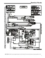
(R) and (W1) thermostat contacts close signaling the control
module (IGN) to run its self-check routine. After the control
has verified that the pres sure switch (PS) contacts are open,
the limit switch (TCO) contacts are closed, and the flame
rollout (FL) switch is closed, the induced draft blower (CBM)
will be energized on high speed for approximately 5 seconds.
After the induced draft blower (CBM) has come up to speed,
the control will verify that the pressure switch (PS) contacts
are closed and switch the induced draft blower to low speed
for 20 second prepurge. The gas valve (GV) is ener gized
in the first stage to permit gas flow and the spark igniter (IP)
is energized. The flame detector (FD) confirms that igni tion
has been achieved within the 7 second trial period.
As the flame detector confirms that ignition has been
achieved the delay to indoor fan on period begins timing and
after approximately 45 seconds, the indoor blower motor
(IDM) will be energized at low speed and will continue to run
during the heating cycle.
Call for 2nd stage after 1st stage:
(R) and (W2) thermostat contacts close signaling a call
for second stage heat. The induced draft motor (CBM) is
energized on high speed and the gas valve on second stage.
After approximately 30 seconds the control energizes the
indoor blower on high speed.
2nd stage satisfied, 1st stage still called:
(R) and (W2) opens, the induced draft blower is reduced to
low speed the gas valve is reduced to first stage. After about
30 seconds the indoor blower motor is reduced to low speed.
1st stage satisfied:
(R) and (W1) opens, the gas valve (GV) will close. The
induced draft blower (CBM) will be de-energized after
approximately 5 seconds postpurge. The indoor blower
motor (IDM) will continue to run for the fan off period (field
selectable 60 or 90 seconds [by jumpers]), then will be de-
energized by the control module.
Comfort Control call for heat (1-stage Comfort Control)
(R) and (W1/W2) (jumped) thermostat contacts close
signaling a call for heat. 1st stage sequence of operation
remains the same as above. 2nd stage heat has a 10 minute
delay from the time of 1st stage ignition.
Comfort Control satisfied:
Safety Sequences
This product is equipped with safety devices to protect against
abnormal conditions.
The temperature limit switch (TCO) is located on the blower
barrier, and can be accessed through the blower compart-
ment. This automatic reset device protects against exces sive
supply air temperature. If this device opens, the gas valve
is immediately closed and will not permit operation until the
limit switch closes.
The rollout switch (RO) is located in the gas compartment
near the inlet of the burners. This is a manual reset device
designed to protect against any form of flame rollout. If this
device is opened the gas valve is immediately de-energized
and the control (IGN) will lockout the system. The rollout switch
(RO) must be reset before operation is allowed to continue.
The pressure switch (PS) is located in the upper right side
of the gas compartment. This automatic device assures
adequate combustion air pressure. If pressure against the
induced draft blower outlet becomes excessive, the pressure
switch will react and shut off the gas valve, until acceptable
combustion pressure is again available.
If the control (IGN) does not sense flame within the first trial
for ignition period, the gas valve will be de-energized. The
control (IGN) will initiate a 60-second interpurge. Following
the interpurge, the control will perform a second ignition
attempt. If the second try is not successful, the control will
start another 60-second interpurge. After the interpurge, a
third attempt will be tried. If the third try is not successful, the
control will lock out.
If loss of flame occurs during a heating cycle, the control
(IGN) will close the gas valve and cycle through the ignition
trial as stated above.
If control lock out occurs, the control (IGN) will retry a complete
ignition sequence in 1 hour.
The control (IGN) can be reset by removing power to the unit
or by turning the thermo stat from ON to OFF for approximately
three seconds, then back ON.
Cooling Cycle
With the comfort control set to COOL and the fan set to
AUTO, the com pressor contactor (CC) and the indoor fan
motor (IDM) are energized.
The energized compressor contactor (CC) completes the cir-
cuit to the compressor (CPR) and a secondary circuit to the
outdoor fan motor (ODM). If the compressor safety controls
are closed, the compressor (CPR) will operate with the outdoor
fan motor (ODM). The indoor fan motor (IDM) will operate.
The thermostat will continue to cycle the compressor and
fans to maintain the desired temperature.
With the comfort control fan set to ON, the indoor fan mo-
tor (IDM) will continue to run regardless of compressor and
condenser fan operation.
(R) and (W1/W2) (jumped) contacts open signaling the control
module to close the gas valve and de-energize the induced
draft blower after approximately 5 second postpurge. The I.D.
blower motor will continue to operate at the current speed for
60 or 90 seconds after the flames are extinguished .
Содержание 4YCY4036B-SF-1H
Страница 9: ...9 Service Facts...
Страница 12: ...Trane 6200 Troup Highway Tyler TX 75707 01 13...


