background image

18

GB

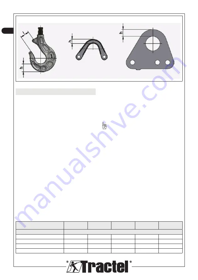
Figure 4-4

5. Measures for safe working

Special risks, which can for instance occur due to 

fatigue and ageing, must be eliminated under the health 

and safety requirements of EC directives.

Thus, the owner of standard lifting equipment is required 

to determine its actual service life. That is determined 

by the after-sales service department as part of the 

annual inspection. When the total theoretical number 

of work cycles under load has been reached or no later 

than after 10 years of service, a general overhaul must 

be carried out. 

All inspections and general overhauls must be carried 

out at the request of the owner of the lifting equipment. 

For  electric  chain  hoists  classified  according  to  DIN 

EN14492-2, the total number of load cycles depending 

on the load condition is shown in table 5-1.

5.1.  Determination of actual use S

The actual use depends on the daily operating time and 

the load conditions.

The determination of the operating time is based on 

the owner’s information or logged by an operating 

data counter. The load conditions are determined in 

accordance with Table 2-1 - Load conditions. From 

these two pieces of information, the annual usage 

time shown in Table 5-2 - Annual Usage Time can be 

deducted.

For electric hoists equipped with a BDE 

(Betriebsdatenerfassungs-Gerät = operating data 

logging device), the actual use can be read out directly 

by our competent employee.

CAUTION:

 The values calculated or read from time 

to time must be entered in the service logbook.

5.2. General overhaul

A general overhaul must be carried out when the 

theoretical limit of the total number of cycles under load 

is reached, or no later than after 10 years if there is no 

work data recording system. In that case, the hoist is 

refurbished to enable it to be used safely for a second 

period of use. The components are tested and changed. 

Testing and approval for a future period of use must be 

carried out by a person skilled in the area and authorised 

by the manufacturer or by the manufacturer itself.

The specialist defines: 


– the new theoretical usage value,


– the maximum operating time until the next general 

overhaul.

The data are recorded in the service logbook. 

Table 5-1: Total number of work cycles under load

Classification according to

DIN EN 14492-2 (ISO 4301-1)

A3 (M3)

A4 (M4)

AS (M5)

A6(M6)

A7 (M7)

Load condition

Number of load cycles over the entire service life

Q2 = 0.50

250,000

500,000

1,000,000

2,000,000

4,000,000

Q3 = 0.63

125,000

250,000

5,000,000

1,000,000

2,000,000

Q4 = 0.80

63,000

125,000

250,000

500,000

1,000,000

Q5 = 1.00

31,500

63,000

125,000

250,000

500,000

Содержание tralift TT 1000

Страница 1: ...g tralift TT tralift TTR Installation operating and maintenance manual English Original manual GB Manuel d installation d emploi et d entretien Fran ais Traduction de la notice originale FR Installati...

Страница 2: ...ling instructions are not followed or not followed adequately The instructions under Caution must be strictly applied RECOMMENDATION This symbol means that following the working and handling instructi...

Страница 3: ...ly friendly manner Safety devices that have been removed during assembly maintenance or repair work must be reinstalled and inspected immediately after such work Follow the frequencies specified in th...

Страница 4: ...ries Type of measurement dBA TT 250 500 a 65 62 59 56 53 b 65 59 53 47 41 TT 125 TT 250 500 single phase a 76 73 70 67 64 b 76 70 64 58 52 TT 1000 TT 1000 single phase a 80 77 74 71 68 b 80 74 68 62 5...

Страница 5: ...tion of the operating maintenance and repair conditions provided by the manufacturer Due to the excellent corrosion resistance of the components located on the load line chain hoists of the tralift TT...

Страница 6: ...he use of the electric chain hoist during its entire service life using the characteristics in Table 2 1 Table 2 2 provides the guidance values for the operating conditions in number of cycles day dep...

Страница 7: ...ad otherwise mainly at reduced load Often at full load otherwise reduced load operation Frequently at full load operation with medium load Regularly at full load Q Load condition loading Table 2 2 Wor...

Страница 8: ...2 2 Overall description Figure 2 1 tralift TT range 1 2 3 4 5 6 7 8 Control box with 1 fall with 2 falls 1 Control unit 2 Rotor shaft 3 Motor 4 Casing 5 Brake 6 Electrical control 7 Reducer 8 Limit sw...

Страница 9: ...ounted upstream from the braking system and incorporated into the rotor shaft It protects the chain hoist from overloads and serves as an upper and lower limit switch An upper and lower limit switch i...

Страница 10: ...ion WARNING Electrical adjustments may only be carried out by authorised specialists To connect the electric chain hoist to the mains the mains cable mains fuse and main switch must be provided by the...

Страница 11: ...ersing the chain in an oil bath or with the help of an oil can The end of the chain must be attached to a flexible wire 1 and inserted through the chain nut 2 into the electric chain hoist The chain 3...

Страница 12: ...ch the reeving jaw 2 to the load hook 1 as shown in Figure 3 7 for TT series hoists and Figure 3 7b for TTR series hoists CAUTION make sure that the suspension is correctly positioned dimension k2 TT2...

Страница 13: ...3 8b Figure 3 9 3 2 3 Limit switch The electric chain hoist is equipped with an integrated limit switch as standard That switch is also suitable as a regular final limit switch with high switching acc...

Страница 14: ...nt see Figure 3 10 Before inserting the chain or while changing the chain the travel switch must be mechanically deactivated by locking the rocker 1 Provision only with model TT 125 Loosen screws 1 2...

Страница 15: ...dditional steel cable of at least 2 mm diameter see Figure 3 12 Note for TT125 see figure 3 12 bis Figure 3 11 Figure 3 12 Figure 3 12 bis Figure 3 13 4 Care and maintenance Malfunctioning electric ho...

Страница 16: ...n 1 4 WARNING All inspections and maintenance work may only be carried out when the hoist is not under load and is out of service The main switch must be switched off The block or the hook must be pla...

Страница 17: ...om time to time 4 2 5 Limit stop CAUTION If the stop plate at the bottom of the casing is defective it must be replaced Check the screw connection at the end and the block assembly and if necessary ti...

Страница 18: ...5 2 Annual Usage Time can be deducted For electric hoists equipped with a BDE Betriebsdatenerfassungs Ger t operating data logging device the actual use can be read out directly by our competent empl...

Страница 19: ...0 320 250 4 1 4 8 1 2 80 B 8 2 2 25 6 630 500 400 320 250 4 4 8 80 B 2 2 25 6 TT500 1 fall 800 630 500 400 320 250 8 2 9 6 2 4 80 B 8 2 1 26 6 800 630 500 400 320 250 8 9 6 80 B 2 1 26 6 TT1000 2 fall...

Страница 20: ...4 1 1 65 0 68 80 B 2 2 0 72 2745 3 2 3 4 3 7 2 75 0 77 5 6 5 9 6 2 2 75 0 77 TT1000 1 fall TT2000 2 falls 100 B 8 2 8 0 57 675 3 8 4 3 5 1 1 45 0 58 7 1 7 4 9 0 1 45 0 58 2 2 3 2790 5 3 6 2 7 8 2 75...

Страница 21: ...poles PN nN Min max currents and starting current 1 115 V 50 Hz 1 230 V 50 Hz IN 380 Imax IA IN 415 power factorN IN 220 Imax IA IN 240 power factorN kW 1 min A A A A TT125 1 fall 71 A 4 4 0 25 1385...

Страница 22: ...2m 240 e h FM 40 M6 3m 360 e h FM 50 M7 4m 360 e h FM 60 M7 4m 360 e h FM 60 Lifting speed 50 Hz Lifting speed 60 Hz Type of motor Number of falls Dead weight 3m stroke Mains connection fuse 400 V ine...

Страница 23: ...ion Les directives de la cat gorie ATTENTION doivent tre rigoureusement respect es RECOMMANDATION Ce symbole indique l observation des directives de travail et de manipulation simplifient le travail e...

Страница 24: ...la taille d homme Ne pas se servir de pi ces de machine comme substitut de tr teaux V rifier les c bles lectriques s il y a des frottements ou des d t riorations Prendre soin d vacuer recueillir et li...

Страница 25: ...n inspection entretien ou r paration aux machines ou appareils d fectueux s assurer d abord de l interruption de courant contr ler r guli rement l quipement lectrique remplacer les c bles d tach s ou...

Страница 26: ...an cha ne le chariot et le chariot d entra nement sous un abri lorsqu ils ne sont pas utilis s Des conditions particuli res d utilisation peuvent tre convenues dans des cas individuels avec le fabrica...

Страница 27: ...upes d utilisation ATTENTION Le chariot sera de la m me classification des m canismes que celle du palan lectrique RECOMMANDATION La d signation du groupe d utilisation du palan lectrique cha ne est i...

Страница 28: ...2 1 tats de sollicitation que l appareil devra fonctionner Tableau 2 1 tats de sollicitation Type de charge Q2 l g re Q 0 50 Q 0 50 Type de charge Q3 moyenne 0 50 Q 0 63 Q 0 63 Type de charge Q4 lour...

Страница 29: ...tion g n rale Figure 2 1 tralift gamme TT 1 2 3 4 5 6 7 8 Bo te de commande 1 brin 2 brins 1 Bo tier de contr le 2 Arbre rotor 3 Moteur 4 Carter 5 Frein 6 Commande lectrique 7 R ducteur 8 Interrupteur...

Страница 30: ...e L accouplement glissement est mont en amont du syst me de freinage et int gr l arbre du rotor Il prot ge le palan cha ne contre les surcharges et sert de limiteur de fin de course haut et bas Un lim...

Страница 31: ...vice le palan lectrique cha ne par des par des personnes comp tentes 3 2 Raccordement 3 2 1 Raccordement lectrique AVERTISSEMENT Les r gales lectriques ne peuvent tre effectu s que par des sp cialiste...

Страница 32: ...ion doivent toujours pr senter de l huile Le graissage s effectue l aide d une huile p n trante type SAE 15W 40 pour engrenage et en plongeant la cha ne dans un bain d huile ou l aide d une burette L...

Страница 33: ...de mouflage 2 au crochet de charge 1 suivant la Figure 3 7 pour les palans de la gamme TT et figure 3 7b pour les palans de la gamme TTR ATTENTION veiller positionner correctement la suspension dimens...

Страница 34: ...k2 Figure 3 8b Figure 3 9 3 2 3 Limiteur de fin de course Le palan lectrique cha ne est quip en standard d un interrupteur de fin de course int gr Celui ci est galement adapt en tant que limitation fi...

Страница 35: ...cha ne ou lors du changement de cha ne l interrupteur de course doit tre inactiv m caniquement par le blocage de la bascule 1 Disposition uniquement avec le mod le TT 125 Desserrez les vis 1 2 et tou...

Страница 36: ...s bo tes cha ne en t le d acier doivent tre assur es l aide d un c ble d acier additionnel de 2 mm minimum voir Figure 3 12 Note pour TT125 se reporter la figure 3 12 bis Figure 3 11 Figure 3 12 Figur...

Страница 37: ...niquement lorsque le palan n est pas sous charge et se trouve hors service L interrupteur principal doit tre coup La moufle ou le crochet doit tre pos sur le sol ou sur la plate forme d entretien Les...

Страница 38: ...e mesur e p riodiquement 4 2 5 But e de fin de course ATTENTION Une plaque but e d fectueuse au bas du carter doit tre remplac e V rifier l assemblage par vis l extr mit et l ensemble constituant la m...

Страница 39: ...ou saisie par un compteur de donn es de fonctionnement L tat de sollicitation est d termin suivant le Tableau 2 1 tats de sollicitation Ces deux indications permettent de d duire la dur e d utilisatio...

Страница 40: ...oids mort 3m lev e course Fusible de raccord au r seau 400 V retarde S rie Capacit de charge kg m min m min kg A TT250 1 brin 400 320 250 200 160 125 8 2 9 6 2 4 80 B 8 2 1 24 6 400 320 250 200 160 12...

Страница 41: ...65 0 68 2 6 3 2 4 1 1 65 0 68 80 B 2 2 0 72 2745 3 2 3 4 3 7 2 75 0 77 5 6 5 9 6 2 2 75 0 77 TT1000 1brin TT2000 2brins 100 B 8 2 8 0 57 675 3 8 4 3 5 1 1 45 0 58 7 1 7 4 9 0 1 45 0 58 2 2 3 2790 5 3...

Страница 42: ...4 5 3420 21 2 20 0 21 5 4 95 0 81 11 0 14 0 4 95 0 87 100 AL 4 4 2 7 1715 10 8 11 2 11 9 1 65 0 79 4 9 5 4 1 65 0 79 100 C 2 2 4 5 3420 20 8 21 6 23 4 4 95 0 81 8 4 9 4 4 95 0 81 Tableau 6 6 Caract r...

Страница 43: ...250 8 2 9 6 2 4 80 B 8 2 1 26 6 TTR500 2 brins 630 500 4 1 4 8 1 2 80 B 8 2 2 28 6 TTR1000 2 brins 1250 1000 4 1 4 8 1 2 100 B 8 2 2 66 10 Tableau 6 9 Caract ristiques lectriques TTR mod les 1 phase G...

Страница 44: ...chend befolgt werden Die Anweisungen unter Achtung m ssen strengstens befolgt werden EMPFEHLUNG Dieses Symbol bedeutet dass das Befolgen der Arbeits und Handhabungshinweise die Arbeit einfacher und ef...

Страница 45: ...aschinenteile nicht als Ersatz f r Montagepl tze verwenden Elektrokabel auf mechanische Besch digungen berpr fen Darauf achten Betriebs und Zusatzprodukte sicher und umweltfreundlich zu beseitigen zu...

Страница 46: ...romversorgung ausgeschaltet ist die elektrischen Ger te regelm ig kontrollieren lose oder besch digte Kabel austauschen beim Ersetzen durchgebrannter Sicherungen sicherstellen dass diese gleichwertig...

Страница 47: ...rt Alternativ kann der Kettenzug das Fahrwerk und der Antriebswagen bei Nichtgebrauch unter einem Schutzdach aufbewahrt werden In bestimmten F llen k nnen mit dem Hersteller besondere Nutzungsbedingun...

Страница 48: ...in der Praxis eingehalten werden m ssen ACHTUNG Das Fahrwerk hat die gleiche Einstufung der Mechanismen wie der Elektrozug EMPFEHLUNG Die Nutzungsgruppe des Elektrokettenzuges ist auf dem Datenschild...

Страница 49: ...betrieben werden In diesem Fall muss das Ger t im leichten Q2 System betrieben werden siehe Tabelle 2 1 Lastzust nde Tabelle 2 1 Lastzust nde Belastungsart Q2 leicht Q 0 50 Q 0 50 Belastungsart Q3 mi...

Страница 50: ...llgemeine Beschreibung Abbildung 2 1 tralift Baureihe TT 1 2 3 4 5 6 7 8 H ngetaster 1 str ngig 2 str ngig 1 Steuereinheit 2 Rotorwelle 3 Motor 4 Geh use 5 Bremse 6 Elektrische Steuerung 7 Getriebe 8...

Страница 51: ...rn Druckfedern das Bremsmoment Die Rutschkupplung ist vor dem Bremssystem montiert und in die Rotorwelle eingebaut Es sch tzt den Kettenzug vor berlastungen und dient als oberer und unterer Endschalte...

Страница 52: ...den Elektrokettenzug von qualifizierten Personen zu installieren und in Betrieb nehmen zu lassen 3 2 Anschlie en 3 2 1 Anschluss elektrisch WARNUNG Elektrische Einstellungen d rfen ausschlie lich von...

Страница 53: ...Die Schmierung erfolgt mit eindringendem Getriebe l Typ SAE 15W 40 durch Eintauchen der Kette in ein lbad oder mit Hilfe einer lkanne Das Kettenende muss mit einem flexiblen Draht 1 verbunden und dur...

Страница 54: ...ken 1 gem Abbildung 3 7 f r Kettenz ge der Baureihe TT und gem Abbildung 3 7b f r Kettenz ge der Baureihe TTR montieren ACHTUNG Stellen Sie sicher dass die Aufh ngung richtig positioniert ist Ma k2 TT...

Страница 55: ...g 3 8 k2 Abbildung 3 8b Abbildung 3 9 3 2 3 Endschalter Der Elektrokettenzug ist serienm ig mit einem integrierten Endschalter ausgestattet Dieser Schalter eignet sich auch als regul rer Endschalter m...

Страница 56: ...1 i 1 1 5 rot 63 31 5 i 1 3 gelb 126 63 i 1 6 blau 252 126 Beschreibung der Einstellung siehe Abbildung 3 10 Vor dem Einsetzen der Kette oder beim Kettenwechsel muss der Fahrschalter durch Verriegeln...

Страница 57: ...ontieren siehe Abbildung 3 13 Den Kettenspeicher installieren und die Kette einf hren siehe Abbildung 3 11 WARNUNG Alle Kettenspeicher aus Stahlblech m ssen mit einem zus tzlichen Stahlseil mit einem...

Страница 58: ...gem der Bedienungsanleitung von Zeit zu Zeit durchgef hrt werden siehe Tabelle 4 1 bersicht ber Inspektionen und Wartung und Tabelle 4 2 bersicht ber Wartungsarbeiten Die Anforderungen der Sicherheit...

Страница 59: ...rkraftbremse ist eine elektromagnetisch bet tigte Einscheibenbremse mit zwei Reibfl chen Die Bremskraft wird von Druckfedern aufgebracht Das Bremsmoment wird beim Ausschalten des Systems erzeugt Verri...

Страница 60: ...nd in Tabelle 5 1 angegeben 5 1 Ermittlung der tats chlichen Nutzung S Die tats chliche Nutzungsdauer h ngt von der t glichen Betriebszeit und den Lastzust nden ab Die Ermittlung der Betriebszeit basi...

Страница 61: ...wicht 3 m Hubl nge Netzan schlusssiche rung 400 V Zeitspanne Baureihe Tragf higkeit kg m min m min kg A TT250 1 str ngig 400 320 250 200 160 125 8 2 9 6 2 4 80 B 8 2 1 24 6 400 320 250 200 160 125 8 9...

Страница 62: ...3 2 4 1 1 65 0 68 80 B 2 2 0 72 2745 3 2 3 4 3 7 2 75 0 77 5 6 5 9 6 2 2 75 0 77 TT1000 1 str ngig TT2000 2 str ngig 100 B 8 2 8 0 57 675 3 8 4 3 5 1 1 45 0 58 7 1 7 4 9 0 1 45 0 58 2 2 3 2790 5 3 6...

Страница 63: ...21 2 20 0 21 5 4 95 0 81 11 0 14 0 4 95 0 87 100 AL 4 4 2 7 1715 10 8 11 2 11 9 1 65 0 79 4 9 5 4 1 65 0 79 100 C 2 2 4 5 3420 20 8 21 6 23 4 4 95 0 81 8 4 9 4 4 95 0 81 Tabelle 6 6 TT elektrische Sp...

Страница 64: ...2 9 6 2 4 80 B 8 2 1 26 6 TTR500 2 str ngig 630 500 4 1 4 8 1 2 80 B 8 2 2 28 6 TTR1000 2 str ngig 1250 1000 4 1 4 8 1 2 100 B 8 2 2 66 10 Tabelle 6 9 TTR elektrische Spezifikationen Einphasen Modell...

Страница 65: ......

Страница 66: ...148185 ind 04 08 20 COPYRIGHT...

Страница 67: ...eralny F igazgat Gener ln editel Director general Gener lny riadite Generalni direktor M Nicolas EMERY TRACTEL S A S RD 619 Saint Hilaire sous Romilly F 10102 ROMILLY SUR SEINE T 33 3 25 21 07 00 Fax...

Страница 68: ...tuo tuotteen myyntiin Euroopan unionin markkinoille SOVELLETTAVAT M R YKSET Katso alta F I SERTIFISERER AT Det utstyret som omtales p motsatt side er i overenss temmelse med de tekniske sikkerhetsreg...

Страница 69: ...eving av materiell Lyft av materiel Podnoszenie sprz tu Anyagemel s Zdv hanie materi lu Ridicare de material Zdv hanie materi lu Dviganje materiala Electric chain hoist Palan chaine lectrique Aparejo...

Страница 70: ...one 33 4 78 50 18 18 Fax 33 4 72 66 25 41 Email info tractelsolutions tractel com GREAT BRITAIN Tractel UK Limited Old Lane Halfway Sheffield S20 3GA United Kingdom Phone 44 114 248 22 66 Email sales...

Отзывы: