


Printed in the Federal Republic of Germany
TR-Electronic GmbH 2018, All Rights Reserved
11/12/2019
TR - ELA - BA - DGB - 0027 - 03
Page 113 of 167
6.3.1.8 Format Signal 11: Position value 1, Sensor 1 (G1_XIST1)
Via signal
G1_XIST1
the current
incremental actual position
of the measuring system is output as a
right-justified 32-bit binary value. Depending on the transmitted preset value, the actual position is
specified unsigned, or signed in two's complement. After switching on the supply voltage/device
RESET the signal
G1_XIST1
is initially loaded with the absolute value. This value is then only
incremented or decremented, depending on the code sequence. An overflow is only generated after
32-bit: 0xFFFFFFFF -> 0x00000000. In the default setting, the preset function has no influence on the
position output, see parameter
Preset affects XIST1
on page 122. Depending on the setting of
the parameter
Encoder Class 4 functionality
, other parameter settings can also directly
affect the position output.
G1_XIST1, Unsigned32
Byte
X+0
X+1
X+2
X+3
Bit
31-24
23-16
15-8
7-0
Data
2
31
– 2
24
2
23
– 2
16
2
15
– 2
8
2
7
– 2
0
6.3.1.9 Format Signal 12: Position value 2, Sensor 1 (G1_XIST2)
Via signal
G1_XIST2
the current
scaled absolute actual position
of the measuring system is output
as a right-justified 32-bit binary value. Depending on the transmitted preset value, the actual position is
specified unsigned, or signed in two's complement. For the output to occur, however, the
corresponding bits must be set in the control words:
G1_STW
: Bit 13 = 1,
STW2_ENC
: Bit 10 = 1
The preset function has a direct influence on the position output. Depending on the setting of the
parameter
Encoder Class 4 functionality
, other parameter settings can also directly affect
the position output.
If a measuring system error is present (
G1_ZSW
, bit 15 = 1), instead of the position a 16-bit error code
is transmitted in data bits 2
0
to 2
15
, see page 146.
The measuring system remains in the error state until the cause of the error has been eliminated and
the error state has been acknowledged with the control word
G1_STW
Bit 15 = 0->1 edge.
G1_XIST2, Unsigned32
Byte
X+0
X+1
X+2
X+3
Bit
31-24
23-16
15-8
7-0
Data
2
31
– 2
24
2
23
– 2
16
2
15
– 2
8
2
7
– 2
0
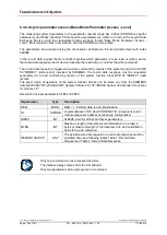
6.3.1.10 Format Signal 39: Position value 3, Sensor 1 (G1_XIST3)
Via signal
G1_XIST3
the current
scaled
absolute
actual position of the measuring system is output
unsigned as a right-justified 64-bit binary value. However, only 32-bit is supported at present, bits 2
32
to 2
63
are therefore set to 0. The preset function has a direct influence on the position output. For
parameter settings to be effective, Class 4 functionality must be enabled under the parameter
Encoder Class 4 functionality
, see page 122.
G1_XIST3, Unsigned64
Word
X+0
X+1
X+2
X+3
Bit
63-48
47-32
31-16
15-0
Data
2
63
– 2
48
2
47
– 2
32
2
31
– 2
16
2
15
– 2
0


