Printed in the Federal Republic of Germany
TR-Electronic GmbH 2010, All Rights Reserved
01/20/2017
TR - ELA - BA - DGB - 0016 - 04
Page 141 of 183
4.2 Switch
– settings
●
The switch position is read-in only in the power-on state, therefore following
modifications can be not recognized!
●
If the switch position is
≠ 0 at power-on, programmings performed by means of
LSS/LMT will be reset to the default settings (Node-ID = 1, 500 kbaud).
4.2.1 Node-ID
●
LA-/LP system
According to the pin assignment, the Node-ID is adjusted by means of two HEX
rotary switches. The adjusted address may be assigned only once in the CAN bus.
- Both HEX rotary switches = 0: LMT or LSS services are active
- One of both HEX rotary switches
≠ 0: Switch position is active
●
LMP system
According to the pin assignment, the Node-ID is adjusted by means of an 8-pole
DIP-switch. The adjusted address may be assigned only once in the CAN bus.
- 8-pole DIP-switch = 0: LMT or LSS services are active
- 8-pole DIP-switch
≠ 0: Switch position is active
4.2.2 Baud rate
●
LA-/LP system
According to the pin assignment, the baud rate is adjusted by means of a HEX
rotary switch.
- Both HEX rotary switches = 0: LMT or LSS services are active
- One of both HEX rotary switches
≠ 0: Switch position is active
●
LMP system
According to the pin assignment, the baud rate is adjusted by means of a 3-pole
DIP-switch.
- 8-pole DIP-switch = 0: LMT or LSS services are active
- 8-pole DIP-switch
≠ 0: Switch position is active
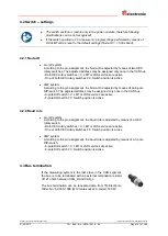
4.3 Bus termination
If the measuring system is the last slave in the CAN segment,
the bus is to be terminated with an external termination resistor
of 121 ohms between CAN_H and CAN_L.
The bus termination can be requested also from TR-Electronic,
Order-No.: 62-000-1366 (M12 male socket, A-
coded, 120 Ω).


