


User's Manual l MBa8x UM 0100 l © 2021, TQ-Systems GmbH
Page 28
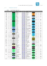
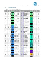
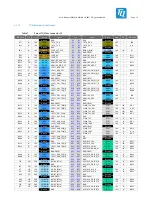
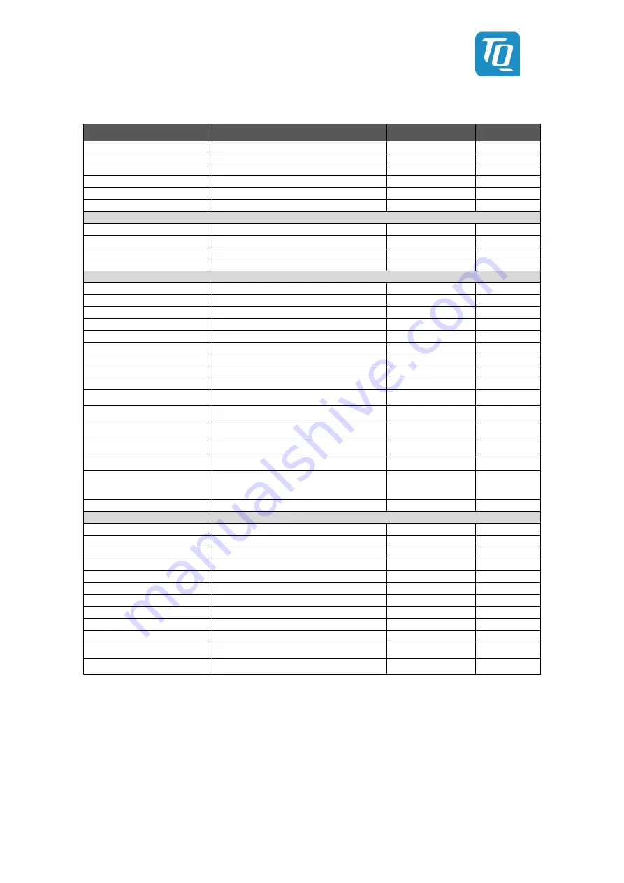
Table 18:
GPIO signals
Source
Alternative / Note
Signal
Voltage level
SCU_GPIO0_02
SCU_LED0
SCU_LED
1.8 V
SCU_GPIO0_03
GPIO0_IO30
EN_1V5_MPCIE
1.8 V
SCU_GPIO0_04
GPIO1_IO00
SWITCH_B#
1.8 V
SCU_GPIO0_05
GPIO1_IO01
EN_3V3_MPCIE
1.8 V
SCU_GPIO0_06
GPIO1_IO02
EN_12V
1.8 V
SCU_GPIO0_07
GPIO1_IO03
SCU_GPIO0_07
1.8 V
M40_GPIO0_00
GPIO0_IO08
M40_GPIO0_00
1.8 V
M40_GPIO0_01
GPIO0_IO09
M40_GPIO0_01
1.8 V
M41_GPIO0_00
GPIO0_IO12
M41_GPIO0_00
1.8 V
M41_GPIO0_01
GPIO0_IO13
M41_GPIO0_01
1.8 V
GPIO0_IO05
-
GPIO0_IO05
1.8 V / 3.3 V
GPIO2_IO02
-
MBUS_RST#
3.3 V
GPIO2_IO03
-
MBUS_INT
3.3 V
GPIO2_IO17
-
GPIO2_IO17
1.8 V
GPIO2_IO21
-
GPIO2_IO21
1.8 V
GPIO1_IO14
-
GPIO1_IO14
1.8 V
GPIO1_IO15
-
GPIO1_IO15
1.8 V
GPIO4_IO07
-
GPIO4_IO07
1.8 V
GPIO4_IO09
-
GPIO4_IO09
1.8 V
GPIO4_IO10
VSELECT Option
GPIO4_IO10
1.8 V
GPIO4_IO11
-
GPIO4_IO11
1.8 V
GPIO4_IO12
-
GPIO4_IO12
1.8 V
GPIO5_IO19
IO voltage depending on SD card speed
GPIO5_IO19
1.8 V / 3.3 V
GPIO5_IO20
IO voltage depending on SD card speed
GPIO5_IO20
1.8 V / 3.3 V
GPIO5_IO23
USDHC1_STROBE /
IO voltage depending on SD card speed
GPIO5_IO23
1.8 V / 3.3 V
GPIO5_IO[29:24]
USDHC2-Interface
GPIO5_IO[29:24]
1.8 V
ESAI1_TX0
GPIO2_IO08
ENET0_INT#
1.8 V
ESAI1_SCKR
GPIO2_IO06
ENET0_RST#
1.8 V
ESAI1_FSR
GPIO2_IO04
ENET1_RST#
1.8 V
ESAI1_SCKT
GPIO2_IO07
USB_RST#
1.8 V
ESAI1_FST
GPIO2_IO05
PCIE_DISABLE#
1.8 V
ESAI1_TX2_RX3
GPIO2_IO10
PCIE_CLK_PD#
1.8 V
ESAI1_TX1
GPIO2_IO09
MIPI_DSI0_BLT_EN
1.8 V
ENET0_REFCLK_125M_25M
GPIO4_IO15
MIPI_DSI1_BLT_EN
1.8 V
ENET1_REFCLK_125M_25M
GPIO4_IO16
MIPI_DSI0_RESET#
1.8 V
ESAI1_TX5_RX0
GPIO2_IO13
MIPI_DSI1_RESET#
1.8 V
ESAI1_TX4_RX1
GPIO2_IO12
FAN_PWR
1.8 V
ESAI1_TX3_RX2
GPIO2_IO11
SWITCH_A#
1.8 V
3.14.8
Display interfaces
3.14.8.1
DisplayPort
In addition to the LVDS and DSI ports, a multifunctional HDMI/DP module is available. The following display specifications can be
used with it:
•
HDMI 2.0a
•
Display port 1.3
•
Embedded Display Port 1.4
On the MBa8x, the interface is implemented as DisplayPort as described in the i.MX8 QM/i.MX8 QXP Hardware Developers Guide.
The series capacitors of 100 nF on the data lines are placed close to the module connector. ESD protection diodes are placed


