User's Manual l MBa8MPxL UM 0100 l © 2022, TQ-Systems GmbH
Page 26
3.3.20
Pin header
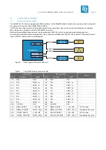
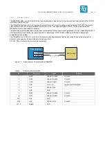
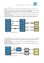
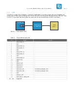
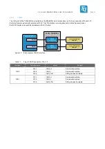
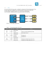
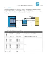
All signals, which are not used on the MBa8MPxL are routed on two pin headers. Most of these signals can be configured as GPIO.
1.8 V, 3.3 V, and 5 V are available on each pin header.
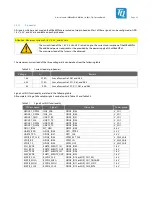
Attention: Maximum current of 1.8 V, 3.3 V, and 5 V rails
The currents load of the 1.8V, 3.3 V and 5 V rails add up to the current consumption of the MBa8MPxL.
The additional power required must be provided by the power supply of the MBa8MPxL.
The maximum load of the fuse must be observed.
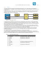
The maximum current load of the three voltage rails can be taken from the following table.
Table 20:
Current load at pin headers
Voltage
I
max
Remark
1.8 V
0.75 A
Sum of currents at X61 and X63
3.3 V
1.75 A
Sum of currents at X11, X61, and X63
5 V
2.2 A
Sum of currents at X7, X11, X61, and X63
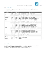
Signals with IO functionality are listed in the following table.
All complete listing of all available signals can be found in Table 22 and Table 23.
Table 21:
Signals with IO functionality
CPU pin name
Signal
Alternative
Power group
USDHC1_DATA1
I2C6_SDA
GPIO2_IO03
V_SD1
USDHC1_DATA0
I2C6_SCL
GPIO2_IO02
V_SD1
USDHC1_CMD
UART1_RX
GPIO2_IO01
V_SD1
USDHC1_CLK
UART1_TX
GPIO2_IO00
V_SD1
USDHC1_DATA3
UART2_RX
GPIO2_IO05
V_SD1
USDHC1_DATA2
UART2_TX
GPIO2_IO04
V_SD1
GPIO1_IO05
M7_NMI
GPIO1_IO05
3.3 V
UART3_RXD
GPIO5_IO26
GPT1_CPTR2
3.3 V
UART3_TXD
GPIO5_IO27
GPT1_CLK
3.3 V
SPDIF_EXT_CLK
GPIO5_IO05
SPDIF_EXT_CLK
V_SAI2_SAI3
SPDIF_RX
GPIO5_IO04
SPDIF_IN
V_SAI2_SAI3
SPDIF_TX
GPIO5_IO03
SPDIF_OUT
V_SAI2_SAI3
SAI1_RXD0
ENET0_EVENT1_IN
GPIO4_IO02
1.8 V
SAI1_RXD1
ENET0_EVENT1_OUT GPIO4_IO03
1.8 V
SAI2_TXD0
ENET1_EVENT2_IN
GPIO4_IO26
1.8 V
SAI2_RXD0
ENET1_EVENT2_OUT GPIO4_IO23
1.8 V
ECSPI2_CS0
ECSPI2_CS0
GPIO5_IO13 or MIPI_CSI1_EN
1.8 V
ECSPI2_MISO
ECSPI2_MISO
GPIO5_IO12 or MIPI_CSI1_TRIGGER
1.8 V
ECSPI2_MOSI
ECSPI2_MOSI
GPIO5_IO11 or MIPI_CSI1_SYNC
1.8 V
ECSPI2_SCLK
ECSPI2_SCLK
GPIO5_IO10 or MIPI_CSI0_RST#
1.8 V


