


Toyota Orderpicker Model
15
Service Manual
Section
9.
Theory of Operation
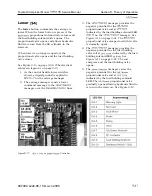
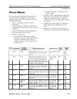
Pinout
Matrix
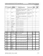
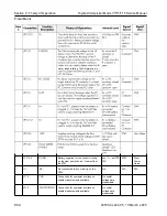
The pinout matrix chart lists functions and
normal voltages of terminals and harness
connector pins. The matrix columns have the
following meanings:
1.
Item
sequential number to aid in
reference.
2.
Connection: the actual wire numbers or
component abbreviations on the electrical
schematic.
Pinout Matrix
b. Identifies possible causes for lack of
proper signal.
5.
Normal Level: the approximate voltage that
should be seen on that wire for the state
indicated. Unless otherwise indicated,
voltages are measured with respect to
B-
at TP4.
6.
Signal Source: the device or connection
that supplies the signal directly to the
wire.
7. Signal User: the device or connection to
which the wire directly delivers the signal.
3 . Function Description: brief definition of
the signal carried on the wire.
4. Theory of Operation:
a. A detailed description of the signal
carried on the wire.
If the signal can be
variable, it indicates the state of a
related component that will cause the
signal to vary.
00700-CL222-05, 1 5
March
2005
9-5 1
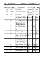
PS
PSI-1
PSI-10
PS
1
-6
PSI-15
AGND
STEER
STEER
STEER
PWM
STEER
PWM
head will not function and code 3,2 is
displayed during self-diagnostics. Check
voltage at
on the STM.
Battery negative for the control circuitry
on the steer power head. It comes from
the STM.
Input from the STM to turn on the circuitry
in one half of the steer transistor circuit for
steering right.
Input from the STM to turn on the circuitry
in one half of the steer transistor circuit for
steering left.
Input from the STM to
PWM
the circuitry in
one half of the steer transistor circuit for
steering in the left.
Input from the STM to
PWM
the circuitry in
one half of the steer transistor circuit for
steering right.
wrt TP4
(B-)
5V no steering
OV steering right
5V no steering.
OV steering left
OV not steering.
steering
fast left
OV not steering.
steering
fast right
STM
STM
STM
STM
STM
Steer
Power
Head
Steer
Power
Head
Steer
Power
Head
Steer
Power
Head
Steer
Power
Head
Содержание 7BPUE15
Страница 1: ...Serial Numbers Service Manual 80 001 and up 7BPUE15...
Страница 2: ......
Страница 5: ......
Страница 22: ...Toyota Orderpicker Model 7BPUE15 Service Manual Section 2 Safety Section 2 Safety 00700 CL222 05 15 March 2005...
Страница 58: ......
Страница 128: ...Toyota Orderpicker Model 7BPUE15 Service Manual Section 6 Codes and Tests Code 4 1 00700 CL222 05 15 March 2005...
Страница 144: ......
Страница 168: ...Toyota Orderpicker Model 7BPUE15 Service Manual Section 7 Component Procedures 00700 CL222 05 15 March 2005 7 24a...
Страница 169: ...Section 7 Component Procedures Toyota Orderpicker Model 7BPUE15 Service Manual 7 24b 00700 CL222 05 15 March 2005...
Страница 170: ...Toyota Orderpicker Model 7BPUE15 Service Manual Section 7 Component Procedures 00700 CL222 05 15 March 2005 7 24c...
Страница 171: ...Section 7 Component Procedures Toyota Orderpicker Model 7BPUE15 Service Manual 7 24d 00700 CL222 05 15 March 2005...
Страница 172: ...Toyota Orderpicker Model 7BPUE15 Service Manual Section 7 Component Procedures 00700 CL222 05 15 March 2005 7 24e...
Страница 173: ...Section 7 Component Procedures Toyota Orderpicker Model 7BPUE15 Service Manual 7 24f 00700 CL222 05 15 March 2005...
Страница 174: ...Toyota Orderpicker Model 7BPUE15 Service Manual Section 7 Component Procedures 00700 CL222 05 15 March 2005 7 24g...
Страница 175: ...Section 7 Component Procedures Toyota Orderpicker Model 7BPUE15 Service Manual 7 24h 00700 CL222 05 15 March 2005...
Страница 176: ...Toyota Orderpicker Model 7BPUE15 Service Manual Section 7 Component Procedures 00700 CL222 05 15 March 2005 7 24i...
Страница 177: ...Section 7 Component Procedures Toyota Orderpicker Model 7BPUE15 Service Manual 7 24j 00700 CL222 05 15 March 2005...
Страница 178: ...Toyota Orderpicker Model 7BPUE15 Service Manual Section 7 Component Procedures 00700 CL222 05 15 March 2005 7 24k...
Страница 179: ...Section 7 Component Procedures Toyota Orderpicker Model 7BPUE15 Service Manual 7 24l 00700 CL222 05 15 March 2005...
Страница 180: ...Toyota Orderpicker Model 7BPUE15 Service Manual Section 7 Component Procedures 00700 CL222 05 15 March 2005 7 24m...
Страница 181: ...Section 7 Component Procedures Toyota Orderpicker Model 7BPUE15 Service Manual 7 24n 00700 CL222 05 15 March 2005...
Страница 182: ...Toyota Orderpicker Model 7BPUE15 Service Manual Section 7 Component Procedures 00700 CL222 05 15 March 2005 7 24o...
Страница 183: ...Section 7 Component Procedures Toyota Orderpicker Model 7BPUE15 Service Manual 7 24p 00700 CL222 05 15 March 2005...
Страница 184: ...Toyota Orderpicker Model 7BPUE15 Service Manual Section 7 Component Procedures 00700 CL222 05 15 March 2005 7 24q...
Страница 185: ...Section 7 Component Procedures Toyota Orderpicker Model 7BPUE15 Service Manual 7 24r 00700 CL222 05 15 March 2005...
Страница 186: ...Toyota Orderpicker Model 7BPUE15 Service Manual Section 7 Component Procedures 00700 CL222 05 15 March 2005 7 24s...
Страница 299: ......
Страница 301: ......
Страница 346: ......
Страница 358: ......
Страница 374: ...Toyota Orderpicker Model 7BPUE15 Service Manual Section A Appendix Section A Appendix 00700 CL222 05 15 March 2005...
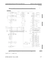
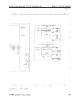
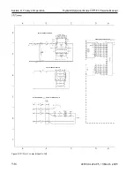
Страница 386: ...Figure A 6 Cont Elec Schematic Sheet I Part 2 of 2 00700 CL222 05 15 March 2005...
Страница 389: ......
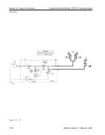
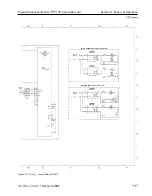
Страница 391: ...Hydraulic Schematic RES Figure A 9 Hydraulic Schematic 00700 CL222 05 15 March 2005...
Страница 399: ...Index Toyota Orderpicker Model 7BPUE15 Service Manual This page intentionallyleft blank 00700 CL222 05 15 March 2005...
Страница 400: ......
Страница 401: ...Printed in the USA...


