Section
9. Theory of Operation
Toyota Orderpicker Model
15 Service Manual
Key Switch (S
1
)
O n
Key
Switch
On
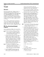
When the key switch is first turned on, the
microprocessor control system performs a
self-diagnostics of certain inputs and outputs.
The self-diagnostics lasts approximately 1
second. Sensor leads are checked for the
correct voltages during the self-diagnostics. If a
problem is detected, the
manager
prevents truck operation and displays a fault
code on the operator display.
With the wire guidance option, the guidance
manager receives battery voltage a t JP2- 1 1 a s
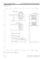
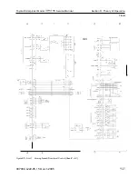
Refer to the schematic in Figure 9-3 on
page 9- 12. (The electrical schematic legend is
on page 9-2.)
The following voltage points are measured with
respect to TP4 (B-):
1. Turning the key switch
1) on supplies
battery voltage from S 1-2 to JPC 1 1 1 (B+
KEY).
2. Battery voltage is a t the following points
on the carriage manager:
JPC 1 1-2 through S2 1 to JPC 1 1-3 (B+
ESTOP)
to
on the
manager
(B+ ESTOP) to
on the
manager (closing relay
3. Battery voltage is a t the following points
on the
manager:
(B+ KEY) to the traction
power amplifier J 1 16
4. Battery voltage is a t the following points
on the
manager a s
ESTOP:
1 through the load-holding
solenoid coil to
1 through the
solenoid coil to
1 through the PC contactor coil
through the brake coil to
5. The
manager receives battery
voltage and produces the following
voltages:
volts
Boost for steer power head
6.
+
12 volts (1
is present a t the following
points on the
manager:
(height
150" switch S29)
(height 180" switch S25)
(optional lift limit switch S24)
(spare switch input)
(steer home sensor
S8)
(optional hour meter)
(to carriage manager)
(MULTI connector)
(steer power head)
7.
+
1 1.3 volts is supplied by the carriage
manager to the following points on the
carriage manager (this is generated from
+
12VP from the
manager):
JPC3-6 (optional lower limit S60)
JPC 12-6 (optional
switch 1,
JPC7-2
1 S2)
JPC7-5
2 S23)
(24" limit switch S6)
1 1 (60" height switch S7)
JPC 12- 15 (optional
switch 2,
S20)
JPC 1 1 (operator display)
8.
volts is present a t JPC2-3 (steer
encoder) on the carriage manager.
9.
volts is present a t PT6-3 steer feedback
encoder) on the
manager.
With the wire guidance option, the guidance
manager receives:
1. Battery positive a t
1 1 a s
This is also used by the power supply on
the guidance manager (GM) to generate
+12 volts which is used by the steer
00700-CL222-05, 1
5 March 2005
Содержание 7BPUE15
Страница 1: ...Serial Numbers Service Manual 80 001 and up 7BPUE15...
Страница 2: ......
Страница 5: ......
Страница 22: ...Toyota Orderpicker Model 7BPUE15 Service Manual Section 2 Safety Section 2 Safety 00700 CL222 05 15 March 2005...
Страница 58: ......
Страница 128: ...Toyota Orderpicker Model 7BPUE15 Service Manual Section 6 Codes and Tests Code 4 1 00700 CL222 05 15 March 2005...
Страница 144: ......
Страница 168: ...Toyota Orderpicker Model 7BPUE15 Service Manual Section 7 Component Procedures 00700 CL222 05 15 March 2005 7 24a...
Страница 169: ...Section 7 Component Procedures Toyota Orderpicker Model 7BPUE15 Service Manual 7 24b 00700 CL222 05 15 March 2005...
Страница 170: ...Toyota Orderpicker Model 7BPUE15 Service Manual Section 7 Component Procedures 00700 CL222 05 15 March 2005 7 24c...
Страница 171: ...Section 7 Component Procedures Toyota Orderpicker Model 7BPUE15 Service Manual 7 24d 00700 CL222 05 15 March 2005...
Страница 172: ...Toyota Orderpicker Model 7BPUE15 Service Manual Section 7 Component Procedures 00700 CL222 05 15 March 2005 7 24e...
Страница 173: ...Section 7 Component Procedures Toyota Orderpicker Model 7BPUE15 Service Manual 7 24f 00700 CL222 05 15 March 2005...
Страница 174: ...Toyota Orderpicker Model 7BPUE15 Service Manual Section 7 Component Procedures 00700 CL222 05 15 March 2005 7 24g...
Страница 175: ...Section 7 Component Procedures Toyota Orderpicker Model 7BPUE15 Service Manual 7 24h 00700 CL222 05 15 March 2005...
Страница 176: ...Toyota Orderpicker Model 7BPUE15 Service Manual Section 7 Component Procedures 00700 CL222 05 15 March 2005 7 24i...
Страница 177: ...Section 7 Component Procedures Toyota Orderpicker Model 7BPUE15 Service Manual 7 24j 00700 CL222 05 15 March 2005...
Страница 178: ...Toyota Orderpicker Model 7BPUE15 Service Manual Section 7 Component Procedures 00700 CL222 05 15 March 2005 7 24k...
Страница 179: ...Section 7 Component Procedures Toyota Orderpicker Model 7BPUE15 Service Manual 7 24l 00700 CL222 05 15 March 2005...
Страница 180: ...Toyota Orderpicker Model 7BPUE15 Service Manual Section 7 Component Procedures 00700 CL222 05 15 March 2005 7 24m...
Страница 181: ...Section 7 Component Procedures Toyota Orderpicker Model 7BPUE15 Service Manual 7 24n 00700 CL222 05 15 March 2005...
Страница 182: ...Toyota Orderpicker Model 7BPUE15 Service Manual Section 7 Component Procedures 00700 CL222 05 15 March 2005 7 24o...
Страница 183: ...Section 7 Component Procedures Toyota Orderpicker Model 7BPUE15 Service Manual 7 24p 00700 CL222 05 15 March 2005...
Страница 184: ...Toyota Orderpicker Model 7BPUE15 Service Manual Section 7 Component Procedures 00700 CL222 05 15 March 2005 7 24q...
Страница 185: ...Section 7 Component Procedures Toyota Orderpicker Model 7BPUE15 Service Manual 7 24r 00700 CL222 05 15 March 2005...
Страница 186: ...Toyota Orderpicker Model 7BPUE15 Service Manual Section 7 Component Procedures 00700 CL222 05 15 March 2005 7 24s...
Страница 299: ......
Страница 301: ......
Страница 346: ......
Страница 358: ......
Страница 374: ...Toyota Orderpicker Model 7BPUE15 Service Manual Section A Appendix Section A Appendix 00700 CL222 05 15 March 2005...
Страница 386: ...Figure A 6 Cont Elec Schematic Sheet I Part 2 of 2 00700 CL222 05 15 March 2005...
Страница 389: ......
Страница 391: ...Hydraulic Schematic RES Figure A 9 Hydraulic Schematic 00700 CL222 05 15 March 2005...
Страница 399: ...Index Toyota Orderpicker Model 7BPUE15 Service Manual This page intentionallyleft blank 00700 CL222 05 15 March 2005...
Страница 400: ......
Страница 401: ...Printed in the USA...

