


Section 7 . Component Procedures
Toyota Orderpicker Model
15 Service Manual
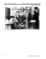
Drive Unit
Drive
Unit
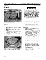
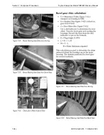
Figure
7-28.
Drive Unit Drain Plug
Remove
1. Remove tractor covers.
2. Remove drive motor. See "Drive Motor" on
page 7-39.
3. Remove center bumper plate (19 mm
socket).
4.
If truck has wire guidance, remove cable
from sensor on front bumper.
5.
Jack and block tractor so drive wheel is
just off floor.
Drive and Brake
Use extreme care whenever the truck
is
jacked up. Never block the truck
between the mast and the floor. Keep
hands and feet clear from vehicle while
jacking the truck. After the truck
is
jacked, place solid blocks beneath it to
support it. DO NOT rely on the jack
alone to support the truck. For details,
See "Jacking Safety" on page
2-1 1.
6. Drain fluid from drive unit. See
Figure 7-28.
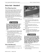
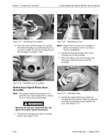
7. Remove 6 bolts (use 10 mm socket head
cap screw wrench) holding drive unit to
tractor. See Figure 7-29.
8. Attach a suitable hoist to drive unit
assembly and lift assembly out of truck.
Installation
1. Using a suitable hoist, lower drive unit
assembly into tractor.
2. Secure drive unit to tractor with six bolts
and adhesive
00590-4609 1-7 1). (Use
10 mm socket head cap screw wrench.)
Torque to 120 ft. lbs. (162.8 Nm).
3. Refill gear box with fluid. See "Lubrication
Specification Chart" on page A-2.
4.
Install drive motor. See "Drive Motor" on
page 7-39.
5.
Install dipstick plug and dipstick.
6. Install prox. switch activation bracket and
secure motor to drive unit with cap
screws.
7. Connect power cables to drive motor.
8. Install steer motor and connect wires to
steer power head. See "Steer Motor" on
page 7-42.
9. Connect brake wires.
10.
If truck uses wire guidance, connect wire
Figure
7-29.
Drive Unit Mounting Bolts (Four Shown)
guidance sensor cable.
1 1. Install bumper plate.
12. Install tractor covers, connect battery and
test truck operation before returning to
service.
00700-CL222-05, 1
5 March 2005
Содержание 7BPUE15
Страница 1: ...Serial Numbers Service Manual 80 001 and up 7BPUE15...
Страница 2: ......
Страница 5: ......
Страница 22: ...Toyota Orderpicker Model 7BPUE15 Service Manual Section 2 Safety Section 2 Safety 00700 CL222 05 15 March 2005...
Страница 58: ......
Страница 128: ...Toyota Orderpicker Model 7BPUE15 Service Manual Section 6 Codes and Tests Code 4 1 00700 CL222 05 15 March 2005...
Страница 144: ......
Страница 168: ...Toyota Orderpicker Model 7BPUE15 Service Manual Section 7 Component Procedures 00700 CL222 05 15 March 2005 7 24a...
Страница 169: ...Section 7 Component Procedures Toyota Orderpicker Model 7BPUE15 Service Manual 7 24b 00700 CL222 05 15 March 2005...
Страница 170: ...Toyota Orderpicker Model 7BPUE15 Service Manual Section 7 Component Procedures 00700 CL222 05 15 March 2005 7 24c...
Страница 171: ...Section 7 Component Procedures Toyota Orderpicker Model 7BPUE15 Service Manual 7 24d 00700 CL222 05 15 March 2005...
Страница 172: ...Toyota Orderpicker Model 7BPUE15 Service Manual Section 7 Component Procedures 00700 CL222 05 15 March 2005 7 24e...
Страница 173: ...Section 7 Component Procedures Toyota Orderpicker Model 7BPUE15 Service Manual 7 24f 00700 CL222 05 15 March 2005...
Страница 174: ...Toyota Orderpicker Model 7BPUE15 Service Manual Section 7 Component Procedures 00700 CL222 05 15 March 2005 7 24g...
Страница 175: ...Section 7 Component Procedures Toyota Orderpicker Model 7BPUE15 Service Manual 7 24h 00700 CL222 05 15 March 2005...
Страница 176: ...Toyota Orderpicker Model 7BPUE15 Service Manual Section 7 Component Procedures 00700 CL222 05 15 March 2005 7 24i...
Страница 177: ...Section 7 Component Procedures Toyota Orderpicker Model 7BPUE15 Service Manual 7 24j 00700 CL222 05 15 March 2005...
Страница 178: ...Toyota Orderpicker Model 7BPUE15 Service Manual Section 7 Component Procedures 00700 CL222 05 15 March 2005 7 24k...
Страница 179: ...Section 7 Component Procedures Toyota Orderpicker Model 7BPUE15 Service Manual 7 24l 00700 CL222 05 15 March 2005...
Страница 180: ...Toyota Orderpicker Model 7BPUE15 Service Manual Section 7 Component Procedures 00700 CL222 05 15 March 2005 7 24m...
Страница 181: ...Section 7 Component Procedures Toyota Orderpicker Model 7BPUE15 Service Manual 7 24n 00700 CL222 05 15 March 2005...
Страница 182: ...Toyota Orderpicker Model 7BPUE15 Service Manual Section 7 Component Procedures 00700 CL222 05 15 March 2005 7 24o...
Страница 183: ...Section 7 Component Procedures Toyota Orderpicker Model 7BPUE15 Service Manual 7 24p 00700 CL222 05 15 March 2005...
Страница 184: ...Toyota Orderpicker Model 7BPUE15 Service Manual Section 7 Component Procedures 00700 CL222 05 15 March 2005 7 24q...
Страница 185: ...Section 7 Component Procedures Toyota Orderpicker Model 7BPUE15 Service Manual 7 24r 00700 CL222 05 15 March 2005...
Страница 186: ...Toyota Orderpicker Model 7BPUE15 Service Manual Section 7 Component Procedures 00700 CL222 05 15 March 2005 7 24s...
Страница 299: ......
Страница 301: ......
Страница 346: ......
Страница 358: ......
Страница 374: ...Toyota Orderpicker Model 7BPUE15 Service Manual Section A Appendix Section A Appendix 00700 CL222 05 15 March 2005...
Страница 386: ...Figure A 6 Cont Elec Schematic Sheet I Part 2 of 2 00700 CL222 05 15 March 2005...
Страница 389: ......
Страница 391: ...Hydraulic Schematic RES Figure A 9 Hydraulic Schematic 00700 CL222 05 15 March 2005...
Страница 399: ...Index Toyota Orderpicker Model 7BPUE15 Service Manual This page intentionallyleft blank 00700 CL222 05 15 March 2005...
Страница 400: ......
Страница 401: ...Printed in the USA...


