P14772
P23480
P14776
P14777
Plastigage
--
ENGINE MECHANICAL
CYLINDER BLOCK (2RZ--FE, 3RZ--F)
EM--65
1 6 . CHE CK CO NNE CTI NG RO D THRUS T CLE ARANCE
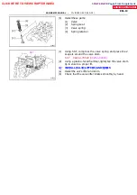
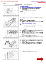
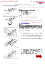
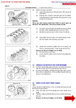
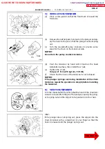
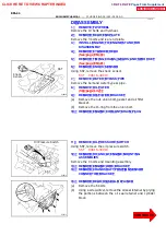
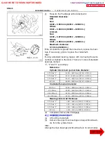
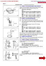
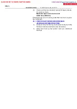
Using a dial indicator, measure the thrust clearance while mov-
ing the connecting rod back and forth.
Standard thrust clearance:
0.160 -- 0.312 mm (0.0063 -- 0.0123 in.)
Maximum thrust clearance:
0.35 mm (0.0138 in.)
If the thrust clearance is greater than maximum, replace the
connecting rod assembly. If necessary, replace the crankshaft.
1 7 . RE MO V E CO NNE CTI NG RO D CAP S AND CHE CK
O I L CLE ARANCE
(a)
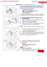
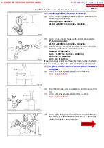
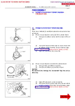
Check the matchmarks on the connecting rod and cap are
aligned to ensure correct reassembly.
(b)
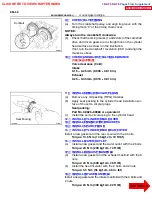
Remove the connecting rod cap nuts.
(c)
Using a plastic--faced hammer, lightly tap the connecting
rod bolts and lift off the connecting rod cap.
HINT:
Keep the lower bearing inserted with the connecting rod cap.
(d)
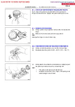
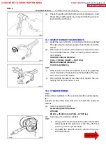
Cover the connecting rod bolts with a short piece of hose
to protect the crankshaft from damage.
(e)
Clean the crank pin and bearing.
(f)
Check the crank pin and bearing for pitting and scratches.
If the crank pin or bearing is damaged, replace the bearings. If
necessary, grind or replace the crankshaft.
(g)
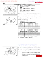
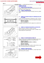
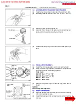
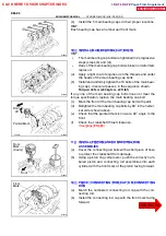
Lay a strip of Plastigage across the crank pin.
(h)
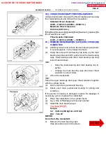
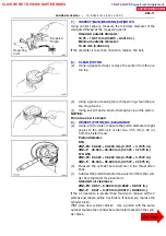
Install the connecting rod cap with the 2 nuts.
Torque:
1st 45 N
∙
m (460 kgf
∙
cm, 33 ft
∙
lbf)
2nd Turn 90
˚
NOTICE:
Do not turn the crankshaft.
(i)
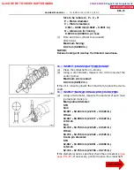
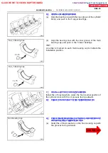
Remove the 2 nuts and connecting rod cap.
(See procedure (b) and (c) above)
CLICK HERE TO VIEW CHAPTER INDEX
Pages From Supplement
3RZ-F,3RZ-FE

