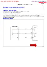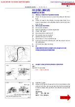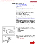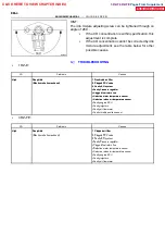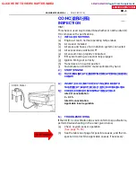
FI4825
Engine
Intake Air Chamber
Exhaust Gas
EGR Valve
Throttle Body
Throttle Valve
VSV
EGR Vacuum
Modulator
ECU
A02260
Engine ECU
EGR
2
E4
Y--B
VSV for EGR
1
2
R--L
IJ4
R--L
IA2
IA1
R--L
2
2
2
2
1
3
5
2
EFI Main Relay
Junction
Connector
W--B
EB
1J
8
1H
6
10A
IG
N
J3
J3
Junction
Connector
From Ignition Switch
Y
2
2
15A
E
F
I
B
atte
ry
W
1
2
W--B
7
B--W
B--R
B--R
22
5
*1 Europe
*2 Except Europe
(*1)
(*2)
Engine RoomR/B
A
A
J1
Drive
Side J/B
B
B
E
ngine
Room
R/
B
DI--178
--
DIAGNOSTICS
ENGINE (2RZ--FE, 3RZ--FE)
EGR System (2RZ--FE).
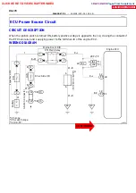
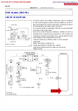
CIRCUIT DESCRIPTION
The EGR system recirculates exhaust gas, which is controlled
to the proper quantity to suit the driving conditions, into the in-
take air mixture to slow down combustion, reduce the combus-
tion temperature and reduce NOx emissions.
The amount of EGR is regulated by the EGR vacuum modulator
according to the engine load.
If even one of the following conditions is fulfilled, the VSV is
turned ON by a signal from the engine ECU. This results in at-
mospheric air acting on the EGR valve, closing the EGR valve
and shutting off the exhaust (EGR cut--off).
Under the following conditions, EGR is cut to maintain
driveability.
Before the engine is warmed up
During deceleration (Throttle valve closed)
Light engine load (amount of intake air very small)
Engine racing
DI1IW--01
CLICK HERE TO VIEW CHAPTER INDEX
Pages From Supplement
3RZ-F,3RZ-FE

