A02281
Engine ECU
FC
14
E6
G--Y
7
7
7
7
Circuit Opening Relay
2
3
5
1
R--L
R--L
12
G--W
BA1
B--W
G--W
Tr
B--R
BC1
Fuel Pump
1
2
W--B
W--B
BA1
BC1
1
*3
J/C
J15
J/C
J23
*3
IK
II
*3
A
A
Passenger Side J/B
IJ1
22
22
IA1
IA2
5
*1
*2
E
F
IR
elay
2
2
2
2
3
2
5
1
E
ngine
Room
R/
B
Y
W--B
EB
A
A
J/C
1J
8
IG
N
1H
6
Drive Side
J/B
J14
J14 C
C
J3
J3
B
B
*3
*3
Junction
Connector
B--W
W--R
6
7
Ignition
Switch
2
2
2
2
2
1
1
15A
EFI
30A
AM2
W
Battery
Europe
Except Europe
2RZ--FE:
*1
*2
*3
DI--174
--
DIAGNOSTICS
ENGINE (2RZ--FE, 3RZ--FE)
Fuel Pump Control Circuit
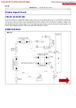
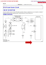
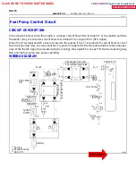
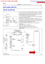
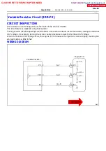
CIRCUIT DESCRIPTION
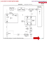
In the diagram below, when the engine is cranked, current flows from terminal ST of the ignition switch to
the starter relay coil and also current flows to terminal STA of engine ECU (STA signal).
When the STA signal and NE signal are input to the engine ECU, Tr is turned ON, current flows to coil of
the circuit opening relay, the relay switches on, power is supplied to the fuel pump and the fuel pump oper-
ates. While the NE signal is generated (engine running), the engine ECU keeps Tr ON (circuit opening relay
ON) and the fuel pump also keeps operating.
WIRING DIAGRAM
DI1IV--01
CLICK HERE TO VIEW CHAPTER INDEX
Pages From Supplement
3RZ-F,3RZ-FE


