A02407
Engine ECU
2
L
NSW
+B
E6
E6
E6
E6
18
19
1
11
Y--B
LG
IC1
7
6
Y--B
LG
2
Neutral
Start Switch
3
6
5
4
R--L
10
R--L
3D
3D
2
1
R--L
15
1
V--Y
V--Y
(A/T)
(A/T)
IC1
8
P--B
STA
IC1
IC1
IC3
Center J/B
C
C
C
C
P--B
(M/T)
P--B
(M/T)
(M/T)
P--B
(A/T)
V--Y
IJ1
(A/T)
V--Y
IJ1 25
(A/T)
V--Y
(A/T)
V--Y
Engine Room R/B
2
B--W
2
2
3
1
5
2
2
Starter Relay
P--B
EB1
2
B--W
W--B
B--W
EB
A
A
J1 J/C
S3
S2
1
1
B--L
Battery
30A
A
M
2
100A
A
LT
40A
A
M
1
W
2
1
1
2
1
2
2
2
II
IH
1
1
2
W--B
Ignition
Switch
7
W
2
8
4
W
R
Engine Room R/B
B
1H
5
10A
G
A
U
G
E
1F
2
Dr
iv
e
S
ide
R
/B
Engine Room R/B
2
2
2
1
7.5A STA
From Ignition Switch
Drive Side R/B
--
DIAGNOSTICS
ENGINE (2RZ--FE, 3RZ--FE)
DI--167
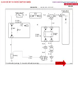
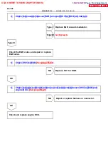
Neutral Start Switch Circuit (3RZ--FE).
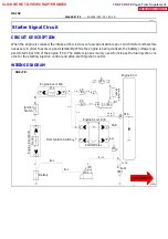
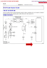
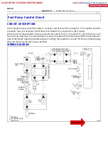
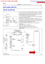
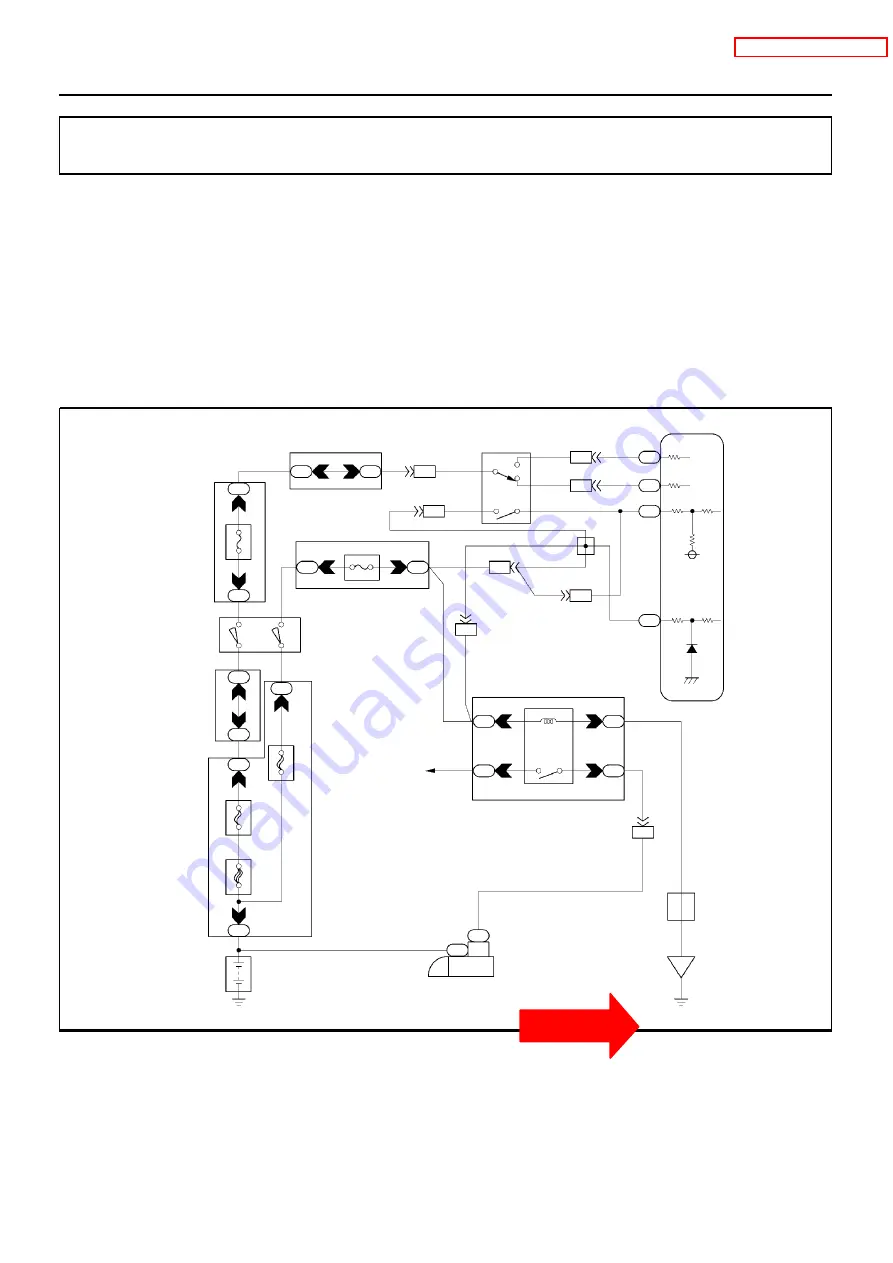
CIRCUIT DESCRIPTION
The neutral start switch goes on when the shift lever is in the N or P shift position. When it goes on terminal
NSW of the engine ECU is grounded to body ground via the starter relay thus the terminal NSW voltage be-
comes 0V. When the shift lever is in the D, 2, L or R position, the neutral start switch goes off, so the voltage
of engine ECU terminal NSW becomes battery voltage, the voltage of the engine ECU internal power source.
If the shift lever is moved from the N position to the D position, this signal is used for air--fuel ratio correction
and for idle speed control (estimated control), etc.
WIRING DIAGRAM
DI1IT--01
CLICK HERE TO VIEW CHAPTER INDEX
Pages From Supplement
3RZ-F,3RZ-FE

