A02257
J14
12
12
#10
#20
#30
#40
Engine ECU
E01
E02
E4
E4
E4
E4
E4
E4
11
25
24
13
26
Injector
No.1
No.2
No.3
No.4
R--L
L
W
R
B--R
B--R
B--R
B--R
BR
BR
BR
ED
IC3
IJ4
12
B--R
B--R
B--R
Ignition Switch
7
6
W--R
2
1
2
2
30A
A
M
2
W
Battery
2RZ--FE
J13
J4
A
A
J3
B
B
*
*
Junc
tion
Connec
to
r
E
ngine
Room
R/
B
DI--158
--
DIAGNOSTICS
ENGINE (2RZ--FE, 3RZ--FE)
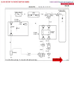
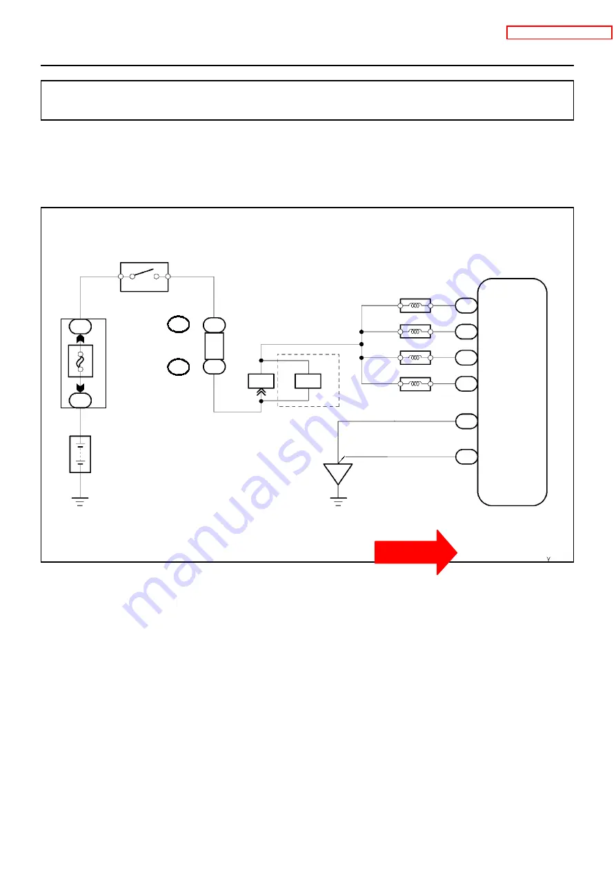
Injector Circuit
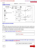
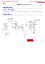
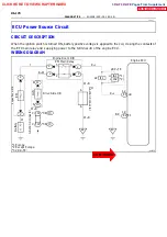
CIRCUIT DESCRIPTION
The injectors are located in the intake manifold. They inject fuel into the cylinders based on the signals from
the engine ECU.
WIRING DIAGRAM
DI1IQ--01
CLICK HERE TO VIEW CHAPTER INDEX
Pages From Supplement
3RZ-F,3RZ-FE


