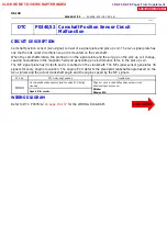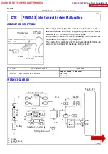
P24397
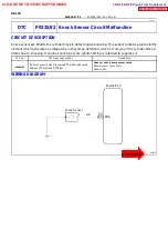
KNK
E5 Connector
FI6510
FI6511
A00068
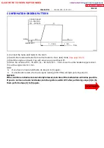
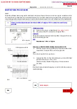
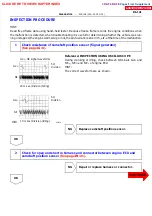
KNK signal waveform
0.5V/
Division
0.5V/
Division
0V
0V
5 m sec./Division
200 sec./Division
--
DIAGNOSTICS
ENGINE (2RZ--FE, 3RZ--FE)
DI--135
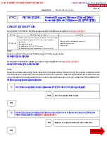
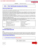
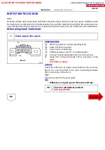
INSPECTION PROCEDURE
HINT:
Read freed frame data using hand--held tester. Because freeze frame records the engine conditions when
the malfunction is detected, when troubleshooting it is useful for determining whether the vehicle was run-
ning or stopped, the engine warmed up or not, the air--fuel ratio lean or rich, etc. at the time of the malfunction.
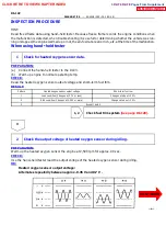
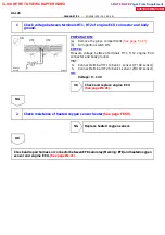
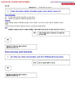
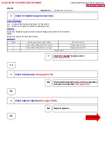
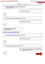
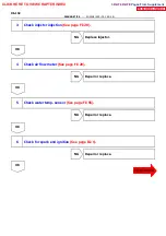
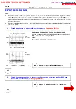
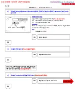
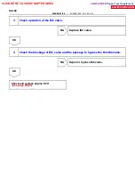
1 Check continuity between terminal KNK of engine ECU connector and body
ground.
PREPARATION:
(a) Remove the glove compartment
).
(b)
Disconnect the E5 connector of engine ECU.
CHECK:
Measure resistance between terminal KNK of engine ECU con-
nector and body ground.
OK:
Resistance: 1 M
Ω
or higher
Reference: INSPECTION USING OSCILLOSCOPE
S
With the engine racing (4,000 rpm) measure between ter-
minal KNK of engine ECU and body ground.
HINT:
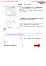
The correct waveform is as shown.
S
Spread the time on the horizontal axis, and confirm that
period of the wave is 151
µ
sec.
(Normal mode vibration frequency of knock sensor:
6.6 kHz).
HINT:
If normal mode vibration frequency is not 6.6 kHz the sensor is
malfunctioning.
NG
CLICK HERE TO VIEW CHAPTER INDEX
Pages From Supplement
3RZ-F,3RZ-FE

