background image

LCM  1010  Instruction  Manual

INTELLIGENT SYSTEM

T£W A

8.2.4 

Primary Status

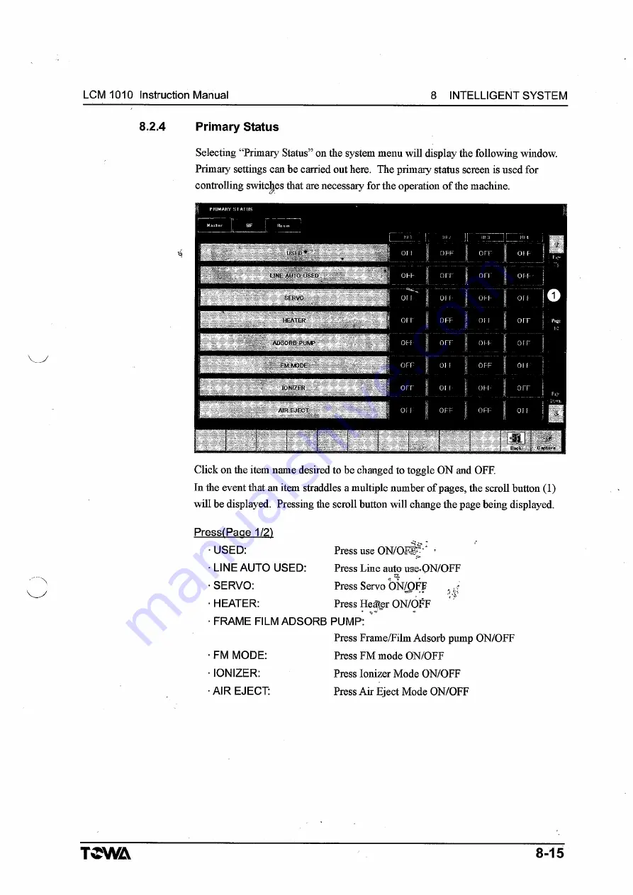
Selecting “Primary Status” on the system menu will display the following window. 

Primary settings can be carried out here.  The primary status screen is used for 

controlling switches that are necessary for the operation o f the machine.

Click on the item name desired to be changed to toggle ON and OFF.

In the event that an item  straddles a multiple number o f pages, the scroll button (1) 

will be displayed.  Pressing the scroll button will change the page being displayed.

PressIPaae 1/21

•USED: 

Press  use ON/ОЩ?"*  -

• LINE AUTO USED: 

Press Line auto use. 

ON/OFF

 SERVO: 

Press  Servo ON/OFF 

. .   r

• HEATER: 

Press  H eifer ON/OFF

• FRAME FILM ADSORB  PUMP:  '

Press Frame/Film Adsorb pump  ON/OFF

• FM  MODE: 

Press F M m ode ON/OFF

• IО NIZE R

Press Ionizer Mode ON/OFF

• AIR EJECT: 

Press Air Eject Mode ON/OFF

8-15

Содержание LCM1010

Страница 1: ...olding System until the information in this manual has been read and fully understood Always keep this manual near the machine so that operators and service personnel can consult it at any time TCWA T...

Страница 2: ...y in mind there remains the potential for dangerous accidents due to operational mistakes or improper daily care and maintenance Before starting operation please read and study this operation manual c...

Страница 3: ...ncerned with machine operation please refer to this manual Maintenance Manual Procedures and safety precautions for cleaning lubrication inspection and parts replacement of the Compression Molding Sys...

Страница 4: ...e knowl edge of machine operation and safety precautions Warning Messages and Definitions The warning messages used in this manual and on the warning stickers affixed to the machine are classified in...

Страница 5: ...eneral use structure and movement of the machine 4 OPERATION SWITCHES AND BUTTONS This section contains information regarding the operation panel and the operation switches and buttons 5 PREPARATION T...

Страница 6: ...es and Functions of Safety Related Equipment 2 27 2 6 Inspection of Safety Related Equipment Operability 2 39 2 7 Protective Gear 2 39 2 8 N oise 2 40 2 9 Exhaust Gas and Dust 2 41 3 OUTLINE OF MACHIN...

Страница 7: ...rate Mounting Procedure 6 12 6 2 7 Substrate Removing Procedure 6 13 6 2 8 Resin Exchange Procedure Charging Resin into the Cartridge 6 14 6 2 9 Resin Exchange Procedure Mounting the Cartridge to the...

Страница 8: ...LCM 1010 Instruction Manual 1 GENERAL INFORMATION 1 GENERAL INFORMATION 1 1 General Information 1 1 rjT 1 2 Customer Service Center 1 2 1 3 Limited Warranty 1 3 a Si T 45WA...

Страница 9: ...1 GENERAL INFORMATION LCM 1010 Instruction Manual TCWA...

Страница 10: ...g TOWA Corporation cannot anticipate every possible circumstance that could involve potential hazards The warnings in this manual are therefore not all inclusive Actions that cannot or must not be con...

Страница 11: ...ge to product http www towajapan co jp english contact i_products index htm TOWA CORPORATION SALES ADMINISTRATION DEPARTMENT 5 Kamichoshi cho Kamitoba Minami ku Kyoto 601 8105 JAPM1 Phone 81 75 692 02...

Страница 12: ...y of the machine to the customer Any defects and or malfunctions which occur during the period of warranty will be repaired and or defeptiye parts replaced as soon as possible and free of charge if an...

Страница 13: ...ing or dropping during transport by the customer 5 Damage caused by fire earthquake flood lightning or other natural disasters 6 Damage caused under abnormal circumstances by the use of substances suc...

Страница 14: ...2 3 2 Points Where Hazard Indication 4 v Stickers Are Affixed 2 6 2 4 Dangerous Areas and Access Procedures 2 21 2 4 1 Dangerous Areas 2 21 2 4 2 Access Procedures for Dangerous Areas 2 25 2 5 Types a...

Страница 15: ...st be performed by a service engineer who has received safety related training an4 instruction and has comprehensive knowledge of the machine 4 t Machine operators should always observe the warnings a...

Страница 16: ...ction as instructed push the Emergency Stop button etc and remain calm Failure to carry out the instructions as indicated may cause malfunction and or result in injury Operation of this machine is res...

Страница 17: ...g of tablets may be harmful to ones health Due to high temperature of the upper part of the mold please be sure that only non flammable resins are inserted Insertion of substances other than non flamm...

Страница 18: ...rring due to malfunctioning high temperature equipment such as heaters motors power sources transformers and the like si This machine uses an ionizer and produces an extremely small quantity of ozone...

Страница 19: ...Be sure that the content of the hazard indication stickers is completely legible Clean or replace stickers if their content and or illustrations become illegible Clean hazard indication stickers with...

Страница 20: ...g Machinery The sticker shown below indicates a danger of a part of ones body getting entangled in rotating or otherwise moving machinery A Exterior Semi Automatic Points where hazard indication stick...

Страница 21: ...rn power off for mechanical parts before maintenance 7 6 Points where hazard indication stickers are affixed A A1 Press Module front door A2 Press Module back door A3 Resin Module front door A4 Resin...

Страница 22: ...MOVING PARTS HAZARD May entangle hands or fingers Close all covers during operation Turn power off for moving parts before maintenance 5 i t m i Points where hazard indication stickers are affixed B...

Страница 23: ...ere hazard indication stickers are affixed B B1 Press Module front door B2 Press Module back door A4 A t w M l N G MOVING PARTS HAZARD May entangle hands or fingers Close all covers during operation T...

Страница 24: ...2 SAFETY LCM1Q10 Instruction Manual C Interior Semi Automatic Points where hazard indication stickers are affixed C Cl Servomotor Resin Handler Unit Up Down Resin Handler Unit Swing 2 10 TCWA...

Страница 25: ...AFETY C Interior Automatic Points where hazard indication stickers are affixed C Cl Servomotor Resin Handler Unit Up Down Resin Handler Unit Swing Cl Servomotor Loader Unit Forward Backward Unloader U...

Страница 26: ...hot surfaces inside the machine D External Semi Automatic A INTERNAL HOT PARTS HAZARD May burn Turn power off and wait for internal parts to cool down before working Points where hazard indication st...

Страница 27: ...bum Turn power off and wait for internal parts to cool down before working nil m t t fT ft Points where hazard indication stickers are affixed D D l Press Module front door D2 Press Module back door D...

Страница 28: ...2 SAFETY LCM1010 Instruction Manual E Interior Semi Automatic Points where hazard indication stickers are affixed E E l Press Module front mold die 2 14 TCWA...

Страница 29: ...LCM1Q10 Instruction Manual 2 SAFETY E Interior Automatic i Points where hazard indication stickers are affixed E E l Press Module front mold die E2 Loder pre heater cover T WA 2 15...

Страница 30: ...if internal parts are touched F Exterior and Interior Semi AutomsjJic Points where hazard indication stickers are affixed F F I Press Module front F2 Press Module rear F3 Resin Module rear F4 Press Mo...

Страница 31: ...OLTAGE HAZARD May cause electric shock or burn Turn power off before maintenance Points where hazard indication stickers are affixed F F I Press Module front F2 Press Module rear F3 Resin Module rear...

Страница 32: ...erior Semi Automatic Points where hazard indication stickers are affixed G G1 Control Cabinet power switch G2 Resin Module main breaker G3 Resin Module noise filter terminal cover G4 Resin Module term...

Страница 33: ...ic Points where hazard indication stickers are affixed G G1 Control Cabinet power switch G2 Resin Module main breaker G3 Resin Module noise filter terminal cover G4 Resin Module terminal cover G5 Hand...

Страница 34: ...that there is danger of the vims infection by way of USB memory H Exterior and Interior So alort for a virus through USB connection Please have the latest virus protection softy are installed J a aau...

Страница 35: ...ith four Press Modules Semi Automatic Dangerous areas at the front side of the machine Dangerous Area 1 r Mold die and its surrounding area _ danger of bums due to touching hot surfaces Slide platen 0...

Страница 36: ...areas danger of bums due to touching hot surfaces Slide platen f danger of being pinched when it moves up down during manual operation Moving parts of the release film handler danger of being pinched...

Страница 37: ...t surfaces Slide platen 0 danger of being snagged in upward downward movement of slide platen during manual operation Moving parts of the release film handler danger of being pinched bruised and caugh...

Страница 38: ...surfaces r Slide platen m J f danger of being pinched when it moves up down during manual operation Moving parts of the release film handler danger of being pinched bruised and caught Frame Loader Fra...

Страница 39: ...n in the up down operation of the slide platen Do not touch a button on the press operation panel carelessly If it is necessaiy to access the press when the mold die is still hot wear clothes with lon...

Страница 40: ...eration 2 Open the press front door and access the press unit 3 To access inside of the press unit use thorough caution in the up down operation of the slide platen Do not touch a button on the press...

Страница 41: ...gency Stop buttons When an Emergency Stop button is pressed the power source will be turned off and the machine will stop immediately When there is danger of bodily harm and or risk of machine damage...

Страница 42: ...2 SAFETY LCM 1010 Instruction Manual NOTE The f gure below is for use with four Press Modules Semi Automatic Emergency Stop button Emergency Stop button 2 28 TCWA...

Страница 43: ...LCM 1010 Instruction Manual 2 SAFETY NOTE The f gure below is for use with four Press Modules Automatic Emergency Stop button TCWA 2 29...

Страница 44: ...Emergency Stop buttons To carry out resetting after Emergency Stop return the Emergency Stop button to its original position by rotating it in the direction of the arrows The Emergency Stop condition...

Страница 45: ...AFETY 3 Power Switch Turn the Power Switch ON to supply power and turn OFF to cut off power NOTE The f gure below is for use with four Press Modules Semi Automatic NOTE The f gure below is for use wit...

Страница 46: ...key Turn the Key Switch ON to enable manual processing and automatic operation NOTE The f gure below is for use with four Press Modules Semi Automatic Key Switch NOTE The f gure below is for use with...

Страница 47: ...ule upward or downward manually select clamp CL via the Press Mode Selection button and then press the Operation button and the UP or DOWN button at the same time for a half second or less The clamp C...

Страница 48: ...2 SAFETY LCM1010 Instruction Manual NOTE The f gure below is for use with four Press Modules Automatic Press Mode Selection button Up button Down button 2 34 TCWA...

Страница 49: ...pened during normal operation stopping or when power has been cut off To open the front baek covers of the Press unit select OFF for the Covers Front Back setting on the Primary Status Press screen an...

Страница 50: ...2 SAFETY LCM1010 Instruction Manual NOTE The f gure below is for use with four Press Modules Automatic Electromagnetic 2 36 TCWA...

Страница 51: ...ower Machine operation status is indicated here R ed Error lit Yellow Alarm lit For TOWA standard Green Automatic Operation lit in LINE AUTO flashing in PROCESS AUTO NOTE The f gure below is forjyse w...

Страница 52: ...2 SAFETY LCM1010 Instruction Manual 2 38 NOTE The f gure below is for use with four Press Modules Automatic TCWA...

Страница 53: ...lated equipment activity is performed periodically by a maintenance engineer 2 7 Protective Gear Whertperforming the types of work shown below wear the corresponding protective gear or the protective...

Страница 54: ...is machine with all safety covered correctly installed is as shown below Noise Level 78dB or less Spec A NOTE The f gure below is for use with four Press Modules Semi Automatic n 1m 1 6m from floor v...

Страница 55: ...peration be sure to activate the factory s ventilation system in concurrence with the instructions detailed in the tablet supply manufacturer s safety data sheet MSDS regarding chemical materials etc...

Страница 56: ...OF MACHINE 3 1 Purpose of Machine 3 1 3 2 Machine Specifications and Exterior Diagrams 3 2 3 2 1 Machine Specifications 3 2 3 2 2 Machine Exterior Diagrams 3 4 3 3 Name and Outline of Each Section 3 6...

Страница 57: ...ions and movements of each section 3 1 Purpose of Machine This machine performs the continuous semiautomatic resin sealing operation for L Fs Whenthe abovementioned air pressure and flow rates cannot...

Страница 58: ...press modules 21 0 kVA Electrical Connection Terminals at right side in the lower part ofmachine Breaker Capacity ELCB 125A Air source Working Air Pressure 0 45 0 6 Mpa 4 4 5 9 kgf cm2 Low air pressu...

Страница 59: ...0 6 Mpa 4 4 5 9 kgf cm2 Low air pressure detection function Manufacturer SMC Model IS1000M 40 Flow Rate 500 Nl min clean dry air Connection Caliber Piping female thread RC 1 2 inch Connection Locatio...

Страница 60: ...ACHINE LCM 1010 Instruction Maniial 3 2 2 Machine Exterior Diagrams Machine exterior and external dimensions are as follows Unit mm NOTE The figure below is for use with four Press Modules Semi Automa...

Страница 61: ...LCM 1010 Instruction Manual 3 OUTLINE OF MACHINE NOTE TJhefigure below is for use with four Press Modules Automatic T WA 3 5...

Страница 62: ...e is composed of the Select Module and Press Modules These Modules are set up as shown below NOTE The f gure below is for use with four Press Modules Semi Automatic Module Names 1 Press Module 2 Resin...

Страница 63: ...igent System display and input 9 Cartridge exchange switch 2 Main operation panel 10 Power switch 3 Press Module operation panel 11 Compressed air supply Rc 1 2 4 Signal tower 12 Electrical power supp...

Страница 64: ...0 Power switch 2 Main operation panel 11 Compressed air supply Rc 1 2 3 Press Module operation panel 12 Electrical power supply 4 Signal tower 13 Cartridge exchange cover 5 Exhaust duct 0150 x H I50 P...

Страница 65: ...ording to the dispensing volume and motor rotation speed specified on the touch panel the motor rotates to dispense resin After dispensing is completed the motor rotates in the reverse direction to pr...

Страница 66: ...specified on the touch panel the motor rotates to dispense resin After dispensing is completed the motor rotates in the reverse direction to prevent resin dripping 3 Substrate release film suction un...

Страница 67: ...re loaded from the bottom by layer 7 Frame Feeder This unit pushes L Fs from the IN Slit Magazine and inspect their directions After inspection this unit transfers L Fs to the loader unit 8 Out Pusher...

Страница 68: ...CM 1010 Instruction Manual 4 OPERATION SWITCHES AND BUTTONS OPERATION SWITCHES AND BUTTONS 4 1 Main Operation Panel 4 3 4 2 Press Operation Panels 4 5 4 3 Other Operation Switches and Buttons 4 8 TCWA...

Страница 69: ...on panels NOTE The f gure below is for use with four Press Modules Semi Automatic 1 Main Operation Panel Refer to 4 1 Main Operation Panel 2 Press Module Operation Panels Refer to 4 2 Press Module Ope...

Страница 70: ...c 1 Main Operation Panel Refer to 4 1 Main Operation Panel 2 Press Module Operation Panels Refer to 4 2 Press Module Operation Panels 3 Touch sensitive Panel for Intelligent System display and input R...

Страница 71: ...ess of the machine condition This button is press lock type and is rotated in the direction of the arrows in order to reset Even when the Emergency Stop button is pressed the power source of the heate...

Страница 72: ...ion press the START button while the lamp is blinking The LINE AUTO button will stop flashing automatically after five seconds 4 START button This button is fokstarting semiautomatic operation Activat...

Страница 73: ...lected nlodewill berindicated by a display lamp 2 Mode Select button 2 This button is for selecting the frame suction manual operation mode ADS film suction manual operation mode FILM FM manual operat...

Страница 74: ...r DOWN button simultaneously To execute origin return operation press this button and the UP button simultaneously 5 START RESET button This button is for resetting each press module Use this button t...

Страница 75: ...S FILM SUCTION MANU FEED fSTEP Li MANU FEED STEP Ri MANU FILM FEED FEED Li MANU FEED FEED R MANU LEAK MANU ADS S MANU FM ADS M MANU CHASE SHUTTER MANU LOCK FILM BRAKE L R MANU PRESS COVER OPEN CLOSE K...

Страница 76: ...ine will stop immediately regardless of the machine condition This button is press lock type and is rotated in the direction of the arrows in order to reset Even when the Emergency Stop button is pres...

Страница 77: ...right side of the resin module For resin module operation J For the manual operation first connect the Handy Console Ten Key to the module T Then input a charge number using the ten key and press the...

Страница 78: ...4 OPERATION SWITCHES AND BUTTONS LCM1010 Instruction Manual NOTE The f gure below is for use with four Press Modules Automatic 4 10 TCWA...

Страница 79: ...use the Emergency Stop button unless there is danger of bodily harm or machine damage or when it is necessary to stop operation for maintenance or inspection work Unwarranted use of this button can l...

Страница 80: ...peration Handy Console Handling Module Side connection For handling module operation For the manual operation first connect the Handy ConsoleT ib Key to the module Then input a charge number using the...

Страница 81: ...ON 5 1 Pre Operation Preparation 5 1 5 1 1 Pre Operation Confirmation Items 5 1 5 1 2 Power ON OFF Procedures 5 2 a 5 1 3 Air Supply Valve ON OFF Procedures 5 3 5 2 EMERGENCY STOP and R e s t a r t 5...

Страница 82: ...garbage on the floor Clean the floor if it is stained with water and or oil or littered with garbage Make sure that there is nothing forgotten in the area of any parts that can move especially in and...

Страница 83: ...ocedures in order to protect the machine from any electrical problems and or power surges Power ON Procedure 1 2 Power OFF Procedure 2 1 NOTE Normally all the no fuse breakers in the control box must...

Страница 84: ...tem related issues Air Supply ON Procedure 1 2 Air Supply OFF Procedure 2 1 Be sure to close all covers and doors There is a danger of injury due to unexpected movement of devices during the process o...

Страница 85: ...rocedures below A CAUTION Do not use any of these Emergency Stop buttons unless there is ganger of bodily harm and or risk of machine damage Unwarranted use of these buttons can lead to malfunction an...

Страница 86: ...LCM1010 Instruction Manual 5 PREPARATION TCWA 5 5...

Страница 87: ...them ON a USED Press Module b LINE AUTO USED Press Module c SERVO Press Module d HEATER Press Module e FRAME FILM ADSORB PUMP Press Module f FM MODE Press Module g AIR EJECT Press Module h SERVO Resi...

Страница 88: ...5 Release Film Winding Procedure 6 10 6 2 6 Substrate Mounting Procedure 6 12 6 2 7 Substrate Removing Procedure 6 13 6 2 8 Resin Exchange Procedure Charging Resin into the Cartridge 6 14 6 2 9 Resin...

Страница 89: ...6 OPERATION LCM 1010 Instruction Manual 6 4 Errors and Alarms 6 28 6 4 1 Error and Alarm Displays 6 28 6 4 2 What to do when errors and alarms occur 6 29 6 5 Resetting Immediate Stop 6 30 S 4 TCWA...

Страница 90: ...is the risk of electric shock If the power indication lamp does not light up confirm the electricity supply from the factory facility to the machine If the Windows screen is not displayed make sure th...

Страница 91: ...Module SARVO BUZZER FM PUM P P b Press Module two screens USED LINE AUTO USED SERVO HEATER FRAME FILM ADSORB PUMP FM MODE IONIZER AIR EJECT FILM HANDLER LEFT FILM HANDLER RIGHT COVER FRONT COVER REAR...

Страница 92: ...OPERATION button and the UP button on the Operation Panel simultaneously The Press will return to its original positions After setting up a release film resin and workpiece LCM1010 becomes ready for...

Страница 93: ...caution Otherwise your hand or body may be caught in the moving parts near the release film unit resulting in injury There are hot parts around the release film unit If you touch these parts carelessl...

Страница 94: ...CM1010 Instruction Manual 6 o p e r a t io n TCWA NOTE The f gure below is for use with four Press Modules Semi Automatic 5 6 NOTE The f gure below is for use with four Press Modules Automatic 5 6 6 5...

Страница 95: ...the covers will not accidentally open To open the covers select a cover to be opened on the cover monitor at the front of the unit or on the automatic operation screen For details refer to the intell...

Страница 96: ...film left empty notice A53 03 A63 03 A73 03 A83 03 Release film right empty notice A53 04 A63 04 A73 04 A83 04 Release film left full A53 05 A63 05 A73 05 A83 05 Release film right full A53 06 A63 06...

Страница 97: ...ivated remove the wound release film according to the following procedure 0 Open the cover at the press rear cover 2 Raise the lever that locks the winding roller Cut the release film 4 Remove the rol...

Страница 98: ...e winding roller 4 Set the knob and confirm that neither the film nor the empty wick slip Distance collars 2 Wick of film Bolts 3 2 About changing the width of the release film of row type 1 Screw the...

Страница 99: ...elease film with the film setup jig and twist it by 90 3 Insert the jig into the clearance between the intermediate plate and the mold die 4 Open the press rear cover and rempve the film setup jig 5 A...

Страница 100: ...h of the OPE button and UP button simultaneously for 0 5 seconds or less 8 Wind the release film through manual operation Select FILM with the selection button 2 For example to wind the film on the ri...

Страница 101: ...ading jig positioning block in a square hole at the center of the intermediate plate 4 Lower the lever and press the loading jig against the upper die 5 Turn ON the substrate vacuum operation with the...

Страница 102: ...loading jig positioning block in a square hole at the center ofthe intermediate plate 3 Lower the lever and press the unloading jig against the upper die 4 Turn OFF the substrate vacuum operation with...

Страница 103: ...resin with an agitating degassing device with vacuum function To mix and degas resin select a method suitable for resin characteristics 3 Pour resin into the resin cartridge for LCM In this step be c...

Страница 104: ...al 6 OPERATION A CAUTION Be careful that air bubbles will not enter the clearance of the O ring Air bubbles can be easily removed by lightly sliding the plunger up down with the cartridge held somewha...

Страница 105: ...en viewed from the front front side press the RIGHT button When each button is pressed the lamp for the cartridge to be exchanged lights and the machine is set to the cartridge exchange mode The resin...

Страница 106: ...removed Remove the cartridge by turning it counterclockwise 7 Mount a new cartridge prepared Screw in the cartridge by turning it clockwise 8 Close the right side cover Keep the CARTRIDGE EXCHANGE bu...

Страница 107: ...applied to inside of the cartridge which causes a little rein leakage NOTE The jacket is completely locked in this step Collect resin that has leaked 11 Attach a newly prepared tip nozzle dispensing...

Страница 108: ...sure that the nozzle is sStvertical If the nozzle is tilted adjust the nozzle angle 2 Eliminate resin that has hardened on the mold die Weigh an amount of resin with an electronic balance 3 Repeat th...

Страница 109: ...anual Pot life resin life span setting procedure 1 Click on the setting button for each dispenser 2 Click on the CHANGE button and enter a resin mixing date time and pot life 3 Click on the OK button...

Страница 110: ...for jnolded substrates becomes full an alarm occurs When an alann occurred insert remove magazines according to the following procedures Inserting Removing Magazine 1 Press and hold the arrow button f...

Страница 111: ...6 OPERATION LCM 1010 Instruction Manual 6 22 TCWA...

Страница 112: ...frame handling pre heats two frames and transfers them to the specified Press Module The frame handling completes its operation when it comes back to the standby position RESIN LOADING process The re...

Страница 113: ...Module are ON The air eject function and FM mode of selected Press Module are ON The selected Press Module has returned to the origin The FM pump of the Resin Module is ON FRAME LOADING process starti...

Страница 114: ...panel The machine starts PROCESS AUTO operation If required conditions are not satisfied the process name will be displayed in gray on the function switch monitor and the corresponding button cannot b...

Страница 115: ...ed in LINE AUTO operation via the Auto Operation screen or Primary Status screen When using all of the four Press Modules press the ALL button 2 Pre ss the LINE AUTO button on the main operation panel...

Страница 116: ...AUTO and the STOP buttons on the main operation panel and the corresponding unit will stop after one cycle operation One cycle stop In the LINE AUTO operation press the LINE AUTO and the STOP and the...

Страница 117: ...e Machine Status window of tfie Intelligent System Please be sure to follow the A instructions set forth in this section Meanings of Signal Tower Error and Alarm Indications Yellow an alarm has occurr...

Страница 118: ...PU I 1 f N K B tt t tt ft J IW M U l ilU fi iw i w ee9 m s w t ire nm 1 8 5 ma 9 1 8 i m b T tm j w Press the Detail button on the top of the Error Alarm Monitor Main screen to switch to the Error Ala...

Страница 119: ...will be extremely hot There is danger of burns if they are touched carelessly Be sure to wear protective gear while working Operators should not open covers or doors or attempt access internal parts...

Страница 120: ...LCM 1010 Instruction Manual 7 DISPOSAL 7 DISPOSAL 7 1 Environment Protection 7 1 7 2 Information Regarding Chemical Content 7 2 TSWA...

Страница 121: ...the laws and ordinances of your locality a Disposal of resin film oils belts filters rubber ducts and electrical lines must be entrusted to government recognized industrial waste management specialis...

Страница 122: ...brominated biphenyl Polybrominated diphenyl ether Pb Hg Cd Cr PBB PBDE Press Module X X X X X X Resin Module X X X X X X Handler Module x X X X X X Remote Control etc X X X X X X As examination regard...

Страница 123: ...e Compression Molding System until the information in this manual has been read and fully understood Always keep this manual near the machine so that operators and service personnel can consult it at...

Страница 124: ...ty in mind there remains the potential for dangerous accidents due to operational mistakes or improper daily care and maintenance Before starting operation please read and study this operation manual...

Страница 125: ...ns concerned with machine operation please refer to this manual Maintenance Manual Procedures and safety precautions for cleaning lubrication inspection and parts replacement of the Compression Moldin...

Страница 126: ...ration Comprehensive knowledge of machine operation and safety precautions Warning Messages and Definitions The warning messages used in this manual and on the warning stickers affixed to the machine...

Страница 127: ...of the machine 4 OPERATION SWITCHES AND BUTTONS This section contains information regarding the operation panel and operation switches and buttons 5 PREPARATION This section explains preparations nec...

Страница 128: ...11 ADJUSTMENT METHODS This section focuses primarily on points in the machine that may require adjustment of servomotor origin position and or adjustment after parts replacement or conversion kit repl...

Страница 129: ...of Safety Related Equipment 2 28 2 6 Confirmation of Operability of Safety Related Equipment 2 40 2 7 Protective Gear 2 41 2 8 Noise 2 42 2 9 Exhaust Gas and D ust 2 43 3 OUTLINE OF MACHINE 3 1 Purpo...

Страница 130: ...6 10 6 4 1 Release Film Handler Unit Automatic 6 11 6 4 2 Dispenser Unit Automatic 6 12 6 4 3 IN Magazine Unit Automatic 6 13 6 4 4 Frame Feeder Unit Automatic 6 18 6 4 5 Frame Loader Unit Automatic 6...

Страница 131: ...8 69 8 5 3 System Setting 8 70 8 5 4 File U tility 8 71 8 6 Other Functions 8 73 8 6 1 Screen Printing 8 73 8 6 2 About the Install D isk L 8 74 v P g w 9 INSPECTION r y 9 1 Daily Inspection J 9 2 9...

Страница 132: ...orward Backward 11 4 11 1 3 Resin handler Swing 11 4 11 1 4 Dispenser Right 11 5 11 1 5 Dispenser Left 11 5 11 1 6 IN Silt Magazine Unit 11 8 11 1 7 OUT Slit Magazine Unit 11 8 11 1 8 Frame Feeder Uni...

Страница 133: ...reasing TOWA Corporation cannot anticipate every possible circumstance that could involve potential hazards The warnings in this manual are therefore not all inclusive Actions that cannot or must not...

Страница 134: ...t i_products index htm TOWA CORPORATION SALES ADMINISTRATION DEPARTMENT 5 Kamichoshi cho Kamitoba Minami ku Kyoto 601 8105 JAPAN Phone 81 75 692 0255 Fax 81 75 692 0276 COMPRESSION MOLDING SYSTEM LCM1...

Страница 135: ...ery of the machine to the customer Any defects and or malfunctions which occur during the period of warranty will be repaired and or defective parts replaced as soon as possible and free of charge if...

Страница 136: ...ling or dropping during transport by the customer 5 Damage caused by fire earthquake flood lightning or other natural disasters 6 Damage caused under abnormal circumstances by the use of substances su...

Страница 137: ...2 3 2 Points Where Hazard IndicatidfrStickers Are Affixed 2 7 2 4 Dangerous Areas and Access Procedures 2 22 2 4 1 Dangerous Areas 2 22 2 4 2 Access Procedures for Dangerous Areas 2 26 2 5 Types and...

Страница 138: ...lated training and instruction and has comprehensive knowledge of the machine Operators should never perform machine maintenance Machine maintenance should always observe the warnings and instructions...

Страница 139: ...as kerosene gasoline benzine thinner alcohol etc near the machine Failure to observe may result in explosion and or fire Do not set up the machine in an area where there is the possibility of flammab...

Страница 140: ...e all been installed before running inspection of the machine Do not open any of the safety covers during machine operation When performing maintenance inspection and or cleaning in the upper area oft...

Страница 141: ...or the floor are wet When inserting resin follow the instructions detailed in the tablet supply manufacturer s safety data sheet MSDS regarding chemical materials etc and be sure to wear protective e...

Страница 142: ...ylic elastic etc are used as well Although these parts are not combustible as such there is the danger of fire occurring due to malfunctioning high temperature equipment such as heaters motors power s...

Страница 143: ...Be sure that the content of the hazard indication stickers is completely legible Clean or replace stickers if their content and or illustrations become illegible Clean hazard indication stickers with...

Страница 144: ...y The sticker shown below indicates a danger of a part of ones body getting entangled in rotating or otherwise moving machinery A Exterior Semi Automatic Points where hazard indication stickers are af...

Страница 145: ...off for mechanical parts before maintenance m m m m Points where hazard indication stickers are affixed A A1 Press Module front door A2 Press Module back door A3 Resin Module front door A4 Resin Modu...

Страница 146: ...W A R N M i S MOVING PARTS HAZARD May entangle hands or fingers Close all covfrs during operation Turn power off for moving parts before maintenance Points where hazard indication stickers are affixe...

Страница 147: ...Points where hazard indication stickers are affixed B Press Module front door B2 Press Module back door r A MOVING PARTS HAZARD May entangle hands or fingers Close all covers during operation Turn pow...

Страница 148: ...LCM1010 Instruction Manual 2 SAFETY C Interior Semi Automatic Points where hazard indication stickers are affixed C Cl Servomotor Resin Handler Unit Up Down Resin Handler Unit Swing T WA 2 11...

Страница 149: ...Interior Automatic J Points where hazard indication stickers are W affixed C O k Cl Servomotor Resin Handler Unit Up Down J Resin Handler Unit Swing Cl Servomotor yi Loader Unit Forward Backward Unlo...

Страница 150: ...LCM1010 Instruction Manual 2 SAFETY E Interior Semi Automatic Points where hazard indication stickers are affixed E E l Press Module front mold die TSWA 2 15...

Страница 151: ...2 SAFETY LCM1010 Instruction Manual E Interior Automatic Points where hazard indication stickers are affixed E E1 Press Module front mold die 2 16 TCWA...

Страница 152: ...ock if internal parts are touched F Exterior and Interior Semi i utomatic VOLTAGE HAZARD May cause electric J B k shock or burn Turn power off before maintenance S l W p i Points where hazard indicati...

Страница 153: ...nterior Automatic A H P VOLTAGE HAZARD May cause electric shock or burn Turn power off before maintenance Points where hazard indication stickers are affixed F F I Press Module rear 2 Resin Module rea...

Страница 154: ...or Interior Semi Automatic Points where hazard indication stickers are affixed G Gl Control Cabinet power switch G2 Resin Module main breaker G3 Resin Module noise filter terminal cover G4 Resin Modul...

Страница 155: ...c Points where hazard indication stickers are affixed G G1 Control Cabinet power switch G2 Resin Module main breaker G3 Resin Module noise filter terminal cover G4 Resih Module terminal cover G5 Hjmdl...

Страница 156: ...ere is danger of the virus infection by way of USB memory H Exterior and Interior u s b f i Be alert for a virus through USB connection 5 Please have the latest virus protection software installed mSE...

Страница 157: ...th four Press Modules Semi Automatic Dangerous areas at the front side of the machine Dangerous Area 1 r Mold die and its surrounding area danger of bums due to touching hot surfaces r Slide platen t...

Страница 158: ...ng areas danger of bums due to touching hot surfaces Slide platen 0 danger of being pinched when it moves up ddwn during manual operation Moving parts of the release film handler danger of being pinch...

Страница 159: ...ing hot surfaces Slide platen e danger of being snagged in upward downWarifmovement of slide platen during manual operation Moving parts of the release film handler danger of being pinched bruised and...

Страница 160: ...surfaces Slide platen 0 y danger of being pinched when it moves up down duiing manual operation Moving parts of the release film handler danger of being pinched bruised and caught Frame Loader Frame...

Страница 161: ...ion in the up down operation of the slide platen Do not touch a button on the press operation panel carelessly If it is necessary to access the press when the mold die is still hot wear clothes with l...

Страница 162: ...ration 2 Open the press front door and access the press unit 3 To access inside of the press unit use thorough caution in the up down operation of the slide platen Do not touch a button on the press o...

Страница 163: ...top buttons 1 When an Emergency Stop button is pressed the power source will be turned olf and As the machine will stop immediately When there is danger of bodily harm and or risk of machine damage pl...

Страница 164: ...LCM 1010 Instruction Manual 2 SAFETY NOTE The f gure below is for use with four Press Modules Semi Automatic 4 T 2W A 2 29...

Страница 165: ...2 SAFETY LCM1010 Instruction Manual NOTE The f gure below is for use with four Press Modules Automatic 4 Emergency Stop button 2 30 T WA...

Страница 166: ...Emergency Stop buttons To carry out resetting after Emergency Stop return the Emergency Stop button to its original position by rotating it in the direction of the arrows The Emergency Stop condition...

Страница 167: ...3 Power Switch Turn the Power Switch ON to supply power and turn OFF to cut off power NOTE The f gure below is for use with four Press Modules Semi Automatic NOTE The f gure below is for use with fou...

Страница 168: ...Switch with key Turn the Key Switch ON to enable manual processing and automatic operation NOTE The f gure below is for use with four Press Modules Semi Automatic Key Switch NOTE The f gure below is...

Страница 169: ...le upward or downward manually select clamp CL via the Press Mode Selection button and then press the Operation button and the UP or DOWN button at the same time for a half second or less The clamp CL...

Страница 170: ...LCM1010 instruction Manual 2 SAFETY T WA NOTE The f gure below is for use with four Press Modules Automatic Press Mode Selection button Operation button ADS FIUI FU SHUT Up button Down button 2 35...

Страница 171: ...pened during normal operation stopping or when power has been cut off To open the front back covers of the Press unit select OFF for the Covers Front Back setting on the Primary Status Press screen an...

Страница 172: ...LCM1010 Instruction Manual 2 SAFETY NOTE The f gure below is for use with four Press Modules Automatic Electromagnetic TSWA 2 37...

Страница 173: ...wer Machine operation status is indicated here Red Error lit Yellow Alarm lit Green Automatic Operation lit in LINE AUTO flashing in PROCESS AUTO For TOWA standard NOTE The f gure below is for use wit...

Страница 174: ...LCM1010 Instruction Manual 2 SAFETY NOTE The f gure below is for use with four Press Modules Automatic T WA 2 39...

Страница 175: ...check once a year Confirm that the message Key Switch OFF is displayed when this switch is turned OFF and that Ready OFF is displayed when this switch is turned ON If the messages are not displayed or...

Страница 176: ...low wear the corresponding protective gear or the protective gear designated by your company s safety standards Type of Work Protective Gear All work related to running of the machine Long sleeved wor...

Страница 177: ...vel of this machine with all safety covered correctly installed is as shown below Noise Level 78dB or less Spec A NOTE The f gure below is for use with four Press Modules Semi Automatic NOTE The f gur...

Страница 178: ...operation be sure to activate the factory s ventilation system in concurrence with the instructions detailed in the tablet supply manufacturer s safety data sheet MSDS regarding chemical materials etc...

Страница 179: ...OF MACHINE 3 1 Purpose of Machine 3 1 3 2 Machine Specifications and Exterior Diagrams 3 2 3 2 1 Machine Specifications 3 2 e 3 2 2 Machine Exterior Diagrams 3 4 3 3 Name and Outline of Each Section 3...

Страница 180: ...ons and movements of each section sp 3 1 Purpose of Machine This machine performs the continuous semiautomatic resin sealing operation for L Fs When the abovementioned air pressure and flow rates cann...

Страница 181: ...VA Electrical Connection Terminals at right side in the lower part ofmachine Breaker Capacity ELCB 3P 125A Air source Working Air Pressure 0 45 0 6 Mpa 4 4 5 9 kgf cm2 Low air pressure detection funct...

Страница 182: ...ssure 0 45 0 6 Mpa 4 4 5 9 kgf cm2 Low air pressure detection function Manufacturer SMC Model IS1000M 40 Flow Rate 500 Nl min clean dry air Connection Caliber Piping female thread RC 1 2 inch Connecti...

Страница 183: ...ACHINE LCM 1010 instruction Manual 3 2 2 Machine Exterior Diagrams Machine exterior and external dimensions are as follows Unit mm NOTE The figure below is for use with four Press Modules Semi Automat...

Страница 184: ...LCM 1010 Instruction Manual 3 OUTLINE OF MACHINE NOTE The figure below is for use with four Press Modules Automatic a T TCWA 3 5...

Страница 185: ...ne is composed of the Select Module and Press Modules These Modules are set up as shown below NOTE The f gure below is for use with four Press Modules Semi Automatic Module Names 1 Press Module 2 Resi...

Страница 186: ...e for Intelligent System display and input 9 Cartridge exchange switch 2 Main operation panel 10 Power switch 3 Press Module operation panel 11 Compressed air supply Rc 1 2 4 Signal tower 12 Electrica...

Страница 187: ...and input 10 Power switch 2 Main operation panel 11 Compressed air supply Rc 1 2 3 Press Module operation panel 12 Electrical power supply 4 Signal tower 13 Cartridge exchange cover 5 Exhaust duct 015...

Страница 188: ...ng to the dispensing volume and motor rotation speed specified on the touch panel the motor rotates to dispense resin After dispensing is completed the motor rotates in the reverse direction to preven...

Страница 189: ...peed specified on the touch panel the motor rotates to dispense resin After dispensing is completed the motor rotates in the reverse direction to prevent resin dripping 3 Substrate release film suctio...

Страница 190: ...re loaded from the bottom by layer 7 Frame Feeder This unit pushes L Fs from the IN Slit Magazine and inspect their directions After inspection this unit transfers L Fs to the loader unit 8 Out Pusher...

Страница 191: ...3 OUTLINE OF MACHINE LCM 1010 Instruction Manual 3 12 TSWA...

Страница 192: ...1010 Instruction Manual 4 OPERATION SWITCHES AND BUTTONS 4 OPERATION SWITCHES AND BUTTONS 4 1 Main Operation Panel 4 3 4 2 Press Operation Panels 4 5 4 3 Other Operation Switches and Buttons 4 8 5 TC...

Страница 193: ...4 OPERATION SWITCHES AND BUTTONS LCM 1010 Instruction Manual T WA...

Страница 194: ...n panels NOTE The f f gure below is for use with four Press Modules Semi Automatic 1 Main Operation Panel Refer to 4 1 Main Operation Panel 2 Press Module Operation Panels Refer to 4 2 Press Module Op...

Страница 195: ...c 1 Main Operation Panel Refer to 4 1 Main Operation Panel 2 Press Module Operation Panels Refer to 4 2 Press Module Operation Panels 3 Touch sensitive Panel for Intelligent System display and input R...

Страница 196: ...of the machine condition This button is press lock type and is rotated in the direction of the arrows in order to reset Even when the Emergency Stop button is pressed the power source of the heater w...

Страница 197: ...tion press the START button while the lamp is blinking The LINE AUTO button will stop flashing automatically after five seconds 4 START button This button is Restarting semiautomatic operation Activat...

Страница 198: ...selected niodewill be indicated by a display lamp 2 Mode Select button 2 This button is for selecting the frame suction manual operation mode ADS film suction manual operation mode FILM FM manual ope...

Страница 199: ...the UP or DOWN button simultaneously To execute origin return operation press this button and the UP button simultaneously START RESET button This button is for resetting each press module Use this b...

Страница 200: ...ANU ADS FILM SUCTION MANU FEED fSTEP LI MANU FILM FEED STEP R1 MANU FEED FEED L MANU FEED FEED MANU LEAK MANU FM ADS S MANU ADS M MANU CHASE SHUTTER MANU LOCK FILM BRAKEIL R MANU PRESS COVER OPEN CLOS...

Страница 201: ...achine will stop immediately regardless of the machine condition This button is press lock type and is rotated in the direction of the arrows in order to reset Even when the Emergency Stop button is p...

Страница 202: ...e right side of the resin module For resin module operation A CAUTION For the manual operation first connect the Handy Console Ten Key to the module e s f f Then input a charge number using the ten ke...

Страница 203: ...4 OPERATION SWITCHES AND BUTTONS LCM1010 Instruction Manual NOTE The f gure below is for use with four Press Modules Automatic 4 10 T W A...

Страница 204: ...use the Emergency Stop button unless there is danger of bodily harm or machine damage or when it is necessary to stop operation for maintenance or inspection work Unwarranted use of this button can l...

Страница 205: ...e operation Handy Console Handling Module Side connection For handling module operation For the manual operation first connect the Handy ConsoleTSu to the module Then input a charge number using the t...

Страница 206: ...TION 5 1 Pre Operation Preparation 5 1 5 1 1 Pre Operation Confirmation Items 5 1 5 1 2 Power ON OFF Procedures 5 2 5 1 3 Air Supply Valve ON OFF Procedures 5 3 5 2 EMERGENCY STOP and Restart 7 5 4 v...

Страница 207: ...rbage on the floor Clean the floor if it is stained with water and or oil or littered with garbage Make sure that there is nothing forgotten in the area of any parts that can move especially in and ar...

Страница 208: ...procedures in order to protect the machine from any electrical problems and or power surges Power ON Procedure 1 2 Power OFF Procedure 2 1 NOTE Normally all the no fuse breakers in the control box mus...

Страница 209: ...m related issues Air Supply ON Procedure 1 2 Air Supply OFF Procedure 2 1 Be sure to close all covers and doors There is a danger of injury due to unexpected movement of devices during the process of...

Страница 210: ...cedures below A CAUTION Do not use any of these Emergency Stop buttons unless there is clanger of bodily harm and or risk of machine damage Unwarranted use of these buttons can lead to malfunction and...

Страница 211: ...LCM1010 Instruction Manual 5 PREPARATION TSWA 5 5...

Страница 212: ...h them ON a USED Press Module b LINE AUTO USED Press Module c SERVO Press Module d HEATER Press Module e FRAME FILM ADSORB PUMP Press Module f FM MODE Press Module g AIR EJECT Press Module h SERVO Res...

Страница 213: ...spenser Unit Semi Automatic 6 5 6 3 Replacement Points and Kinds of Conversion Kits Automatic 6 6 6 3 1 Replacement Points Automatic 6 6 6 3 2 Conversion Kits Automatic 6 7 6 4 Conversion Kit Replacem...

Страница 214: ...ems explained in the section 2 SAFETY and then start the operations The operations must be c arried out only by maintenance engineers and service engineers USER QUALIFICATIONS Maintenance engineer Rec...

Страница 215: ...subsection explains the pointer where replacement is necessary and the kinds of replacement parts 6 1 1 Replacement Points Semi Automatic s At the start of production and or when tfie kind of product...

Страница 216: ...ement is necessary are shown below Release Film Handler Unit Press Module Release film roller Unwinding side U Di ancecoHars x 4 4 Release film roller Winding side i I f V Distancecollars x 4 NOTE The...

Страница 217: ...ce the release film roller 1 Open the doors at the front and back of the Press Module 2 Raise the lever that fastens the roller 3 Remove the roller 4 Exchange it to the distance collars with a roller...

Страница 218: ...et which fastens the cartridge 3 Remove the cartridge 4 Replace the cartridge which is suitable for the product type 5 Attach the nozzle head which is suitable for the product type after fastening the...

Страница 219: ...ement Points Automatic At the start of production and or when the kind of product is changed be sure to 4 repmce the conversion kits at the units shown below NOTE The f gure below is for use with fqur...

Страница 220: ...ent is necessary are shown below Release Film Handler Unit Press Module Release film roller Unwinding sid4 e Distance collars x 4 Release film roller Winding side Distance collars x 4 NOTE There are n...

Страница 221: ...REPLACEMENT AND ADJUSTMENT LCM 1010 Instruction Manual In Slit Magazine Unit Handling Module Elevator IN Slit Magazine Receiving Arm V x l IN Slit Magazine Discharge Plate Frame Feeder Unit Handling...

Страница 222: ...ERSION KIT REPLACEMENT AND ADJUSTMENT Frame Unloader Unit Handling Module Out Pusher Unit Handling Module Out Slit Magazine Unit Handling Modul Elevator OUT Slit Magazine Receiving Arm i X 1 OUT Slit...

Страница 223: ...on for conversion kit replacement so that replacement can be easily carried out Target axes IN OUT elevator axis Z Loader Unloader axis X Press Machine Maintenance button 1 Kit Change button 2 YES but...

Страница 224: ...that fastens the roller 3 Remove the roller 4 Exchange it to the distance collars with a roller whose width of release film is suitable for the package type Each press module has four rollers Two rol...

Страница 225: ...which fastens the cartridge 3 Remove the cartridge 4 Replace the cartridge which is suitable for the product type 5j Attach the nozzle head which is suitable for the product type after fastening the...

Страница 226: ...RSION KIT REPLACEMENT AND ADJUSTMENT 6 4 3 IN Magazine Unit Automatic 1 Elevator IN Magazine Receiving Arm Conversion Kit 1 Remove two M5 bolts 1 and replace the IN magazine receiving arm 2 Elevator I...

Страница 227: ...ne Discharge Plate Conversion Kit 1 Remove two M5 bolts 1 and replace the IN magazine discharge plate 2 6 CONVERSION KIT REPLACEMENT AND ADJUSTMENT LCM 1010 Instruction Manual INmagazine discharge pla...

Страница 228: ...IT REPLACEMENT AND ADJUSTMENT 3 IN Magazine Guide Adjustment Remove two M5 bolts 1 to free the magazine guide 2 Set the magazine 3 leave a space between the magazine and the guide with approximately 0...

Страница 229: ...EPLACEMENT AND ADJUSTMENT LCM 1010 Instruction Manual 4 IN Magazine Next Clamper Adjustment Loosen four M5 bolts 1 move the next clamper 2 to the center position 4 of the next magazine 3 and tighten t...

Страница 230: ...three directions of X Y and Z X direction Loosen two M4 bolts 1 and adjust the position Y direction Loosen two M4 bolts 2 and adjust the position Z direction Loosen two M5 bolts 3 and adjust the posit...

Страница 231: ...n Manual 6 4 4 Frame Feeder Unit Automatic 1 Frame Pusher Conversion Kit 1 Remove two 3 bolts 1 and replace the frame pusher 2 When installing the frame pusher make sure that there is no space on the...

Страница 232: ...en the feeder unit and replace the positioning block 2 For the replacement insert the positioning block following the positioning pins which are protruded from the right and left of the kit 2 When ins...

Страница 233: ...d move the laser sensor to the rightmost side 2 Loosen a knurling knob 2 and replace the positioning block 3 3 When mounting the positioning block make sure that there is no space on the attached side...

Страница 234: ...ding the knobs 6 4 Loosen two knurling knobs 7 and pull the knob 8 and remove the preheater plate 9 Both sides are removed in the same way When pulling the heater plate when it i svery hot as there is...

Страница 235: ...e the frame loader unit 4 and remove it from the machine When raising the frame loader unit hold two knurling pins 5 3 When installing the unit carry out an operation in reverse procedures NOTE When i...

Страница 236: ...der Unit Automatic 1 Frame Unloader Conversion Kit 1 Displace the OUT pusher unit 1 to the right side where it does not interfere to enable to remove the frame unloader Loosen a bolt knob 2 release pu...

Страница 237: ...der unit 7 and remove it from the machine When raising the frame unloader unit hold two knurling pins 8 4 When installing the unit carry out an operation in reverse procedures NOTE When inserting the...

Страница 238: ...ADJUSTMENT 6 4 7 OUT Pusher Unit Automatic 1 OUT Pusher Conversion Kit Remove two 3 bolts 1 and replace the OUT pusher 2 When installing the OUT pusher make sure that there is no space on the attache...

Страница 239: ...TMENT LCM 1010 Instruction Manual 6 4 8 OUT Slit Magazine Unit Automatic 1 Elevator OUT Magazine Receiving Arm Conversion Kit 1 Remove two M5 bolts 1 and replace the OUT magazine receiving arm Elevato...

Страница 240: ...uction Manual 6 CONVERSION KIT REPLACEMENT AND ADJUSTMENT 2 OUT Magazine Discharge Plate Conversion Kit 1 Remove two M5 bolts 1 and replace the OUT magazine discharge plate 2 OUT magazine discharge pl...

Страница 241: ...T LCM 1010 Instruction Manual 3 OUT Magazine Guide Adjustment Remove two M5 bolts 1 to free the magazine guide 2 Set the magazine 3 leave a space between the magazine and the guide with approximately...

Страница 242: ...ual 6 CONVERSION KIT REPLACEMENT AND ADJUSTMENT 4 OUT Magazine Next Clamper Adjustment Loosen four M5 bolts 1 move the next clamper 2 to the center position 4 of the next magazine 3 and tighten the bo...

Страница 243: ...and adjust the position Y direction Loosen two M4 bolts 2 and adjust the position Z direction Loosen two M5 bolts 3 and adjust the position Adjust the position of clamper in Z direction to move clamp...

Страница 244: ...nlerk Also change the product type data in the Recipe data setting of the intelligent system to be suitable for the changed product type Kecipe Data 6 j PRESS RESIN S I R MAGA INF IN CO U N T SLIT MAG...

Страница 245: ...ata Regarding methods of saving please refer to 9 2 5 Recipe Data Setting of the Intelligent System HAN D LIN G PR FSS i1 RFSIN SMG IN SMG OUT UW DW IJW DW FLD ADJ O G i Mt P osition Speed M otion SI...

Страница 246: ...dule 7 1 7 1 1 Manual Operation Semi Automatic 7 1 7 1 2 Manual Operation Automatic 7 3 7 2 Manual Operation Press v 7 5 7 2 1 Manual Upward and Downward Movement of Press 7 6 7 2 2 Press Return to Or...

Страница 247: ...giovements of the machine s components 7 1 Manual Operation Resin Module Handling Module 7 1 1 Manual Operation Semi Automatic The manual operation of each device of this machine is carried out via t...

Страница 248: ...ownward and Open Close each time the Set button is pressed When the actuator is motorized two charge numbers are assigned one for each the rotation direction CW CCW Start Stop can be toggled via the S...

Страница 249: ...rge number using the ten key and press the S key to operate the s specified device Each Handy Console is fitted with a magnet on its back and can be stuck onto the covers of the modules 4 F l l WARNIN...

Страница 250: ...rd and Open Close each time the Set button is pressed When the actuator is motorized two charge numbers are assigned one for each the rotation direction CW CCW Start Stop can be toggled via the S key...

Страница 251: ...lly Each time the mode select button is pressed the displayed item will change in the following order For example when the CL button is lit upward downward movement of the Press clamp is selected CL U...

Страница 252: ...ement press the OPE button and the Up button simultaneously for 0 5 seconds or less The clamp will move upward b For downward movement press the OPE button and the Down button simultaneously for 0 5 s...

Страница 253: ...responding Press Operating Procedure 4 CL HANU HOU ORG A D S FILH S H U 1 Select ORG using the Press select button 1 2 Then press both of the OPE button and Up button simultaneously for 0 5 seconds or...

Страница 254: ...r at the rear of the press is closed the cycle auto is enabled even while other presses are in operation Line auto inside cannot operate at the cycle auto 2 Then press the OPE and UP buttons simultane...

Страница 255: ...related accidents put on brakes or buffer stops to ensure that the body of the lifter does not move When carrying out maintenance and cleaning of the mold die when it is very hot or when carrying out...

Страница 256: ...preheater with a thermometer and wait until stabilized A CAUTION A CAUTION 8 Carry out press return to origin process Refer to the 7 2 2 Press Origin Return Right after the resin fed into the mold c...

Страница 257: ...Operations Screen 8 5 8 2 3 Menu Screen 8 14 8 2 4 Primary Status 8 15 8 2 5 Recipe Data Settings 8 18 8 2 6 Error Alarm Monitor 8 31 8 2 7 Machine Monitor 8 34 8 3 Device Information Menu 8 36 8 3 1...

Страница 258: ...8 5 System Related Menu 8 67 8 5 1 Password Settings 8 67 8 5 2 Work Time Settings Work Data Setting 8 69 8 5 3 System Setting 8 70 8 5 4 File Utility 8 71 8 6 Other Functions 8 73 8 6 1 Screen Print...

Страница 259: ...gent System 8 1 1 Starting Up the Intelligent System a Double click on the IsSe LCM shortcut ioon on your desktop After starting up screens can be selected and opiated as follows t vf Diagram of Scree...

Страница 260: ...talled Restart the computer Press to restart the FA computer upon which the Intelligent System is installed Cancel Press to return to the previous screen When the system itself shuts down there will b...

Страница 261: ...as been selected 1 Machine Status Display Shows the current status of the machine For a guide to the items shown here please refer to the list of machine status descriptors listed below 2 Movement Int...

Страница 262: ...Process Auto in effect b The production line is running automatically The machine is primed for operations The machine is not primed for operations B Bottom part of the screen A status window is alway...

Страница 263: ...ration 1 Process Auto Displays the Process Auto menu 2 Status Switches to the Primary Status screen 3 Recipe Data Switches to the Recipe Settings screen 4 Error Alarm Switches to the Error and Alarm s...

Страница 264: ...ng in black Aiarm status_ lTilm is full 4 Workpiece status Green Pre molding frame is present Blinking in green Post molding frame is present Light blue frame Film feed is completed Resin indication D...

Страница 265: ...ered for each shot The following data will be displayed for each individual Hold Frame Index Time Machine Time P H Time Compression Time Cure Time Set Cure Time 4 FM Pressure CL Pos CL Spd CL Force CL...

Страница 266: ...r will display the counter data for each individual Press Set values can he fixed for each item an alarm will sound in the event that the current values have superseded the set values In the event tha...

Страница 267: ...ture Lower 1 2 Lower mold temperature If the monitor temperature value is higher than J Set Temp Temp ALARM 4t is displayed in orange If the monitor temperature value is lower than Set Temp Temp ALARM...

Страница 268: ...emory record Therefore when the memory for such a part is removerLfrue to machine trouble or the like please remember to delete the corresponding memory on this screen In the event of a memory deletio...

Страница 269: ...W t W o Handling Back Cover P 1 Front Cover Resin Right Back Cover Handling Left Cover P 1 Rear Covet FBsht Cover Handling Front Cover P 2 Front Cover Resin Right F Cover P 2 Rear Cover Bs3 Front Gov...

Страница 270: ...d Time Pot Life Adjustment of Cartridge Dispensing Test A volume of resin remaining in the cartridge calculation value can be monitored Enter a date time when the resin was mixed When 2 component mixi...

Страница 271: ...firm the press to be loaded In the event of a mistake press the Press button for the press desired to be loaded in order to select it 2 Press the START button Unloading 1 When any of the Frame Unloadi...

Страница 272: ...Settln2__ System Setting File Utility Version The machine operation information screen This screen displays the temperature for each different unit type This screen tracks the status of each shot This...

Страница 273: ...he item name desired to be changed to toggle ON and OFF In the event that an item straddles a multiple number of pages the scroll button 1 will be displayed Pressing the scroll button will change the...

Страница 274: ...SE CHANGE MODE Chase change ON OFF ILLUMINATION Press Illumination ON OFF COVER F Press Front Cover Lock Unlock COVER R Press Rear Cover Lock Unlock Row type PresstPaae 2 21 FILM HANDLER Release Film...

Страница 275: ...e ILLUMINATION Resin Module illumination ON OFF SERVO Resin Module Servo ON OFF BUZZER Buzzer ON OFF FM PUMP FM Pump ON OFF Handling Module ILLUMINATION Handling Module illumination ON OFF SERVO Handl...

Страница 276: ...ant data will t egfisplayed Selecting the data on display will bring up the data entry screen r ____ _________________ 1 Show Recipe Name Displays the currently set recipe name 2 Switch Modules Press...

Страница 277: ...o Press 4 Screen displayed in other conditions After input is complete press the OK _hutton Some data items may have limitations as to their acceptable inpit value J 2 Press the OK button to set the d...

Страница 278: ...ting programs and spreadsheet applications alike n S External File Operation Menu R Export I F6 Import ES C Cancel Multiple data can be selected and processed Export This procedure is for saving exter...

Страница 279: ...I L i b I Al l EFD Esc3 O K G i n t f l 2 Designate a location drive then select the data to be imported from the list The selected data will be highlighted 3 Click on the OK button The selected data...

Страница 280: ...le 1 Press the File button and select Load from the displayed menu ESI I PA l I i rii i C fM i i Esc 2 Select the data item to be retrieved from the list then click on the OK button The selected data...

Страница 281: ...utton and select Edit from the displayed menu m u u r CF3J 11 41 MoYe I Rename I New 1 EF9J I I 0 1 2 Select Copy 3 Select the original data to be copied In field 1 enter a Number Name of the Product...

Страница 282: ...and select Edit from the displayed menu 2 Select M o I M J Li si m u L H J 1 01 06 0 08 If PrV 11 r r i i I 3 Enter the number of the position to be moved to field 1 A input keyboard will be displayed...

Страница 283: ...ta to be edited and in field 1 enter a Number Name of the Product Type or a comment There is an input limit of 30 characters Press on the input items and the input keyboard will be displayed 4 Press t...

Страница 284: ...1 NEWNAME4 200408 30 12 34 0 2004 0305113521 2004 8 512 52 29 i P A C I I i c in i i F51 3 Select the location for the new data Infield 1 enter a Number Name of the Product Type or a comment There is...

Страница 285: ...U i im I 9 E s c O l O in if 2 Select the item to be deleted from the list Selected data will be highlighted on screen 3 Press the OK button The selected data items will be deleted from the system in...

Страница 286: ...urn to the previous screen H D FI D FW BW IW RW L _ i I AR i Position Speed Mono S H I MAGA INF IN COUNT SLIT MAGA INL OUT COUNT FRAME FFFD FR FM PIY F ttD COUNT FRAMf LOADLR PRLIITAT TIMF L F PH TtM...

Страница 287: ...value and suck back volume in the unit of gram g Dispensing b e ttin g D ensity o f Resin Dispensing Volume 1 0 1 0 0 g c c 3 0 3 0 g Volume c c Dispensing Volum e O ffse t L 0 0 0 0 g Dispensing V o...

Страница 288: ...pensing pattern by touching the screen 1 Touch eachJTield at the center of the screen in sequence 2 If you touch a coordinate display field on the left of the screen the corresponding number will be s...

Страница 289: ...w Details of the error and alarm occurring at that time are displayed Up to 18 current errors and alarms are displayed in order of occurrence Operations of Touch Sensitive Screen Double click on a dis...

Страница 290: ...RROR ALARM MONITOR Errors are displayed for each unit The numbers corresponding to any currently occurring errors or alarms are highlighted Operations of Touch Sensitive Screen Double click on a displ...

Страница 291: ...n o s i s E r r o r DDE DH A d d e s s r e a d e x c e p 1 i on e r r o r 1 0 A d d r e s s w r i i e e x c e p l i o n e r r o r D 1 2 Q H F P U e x c e p t i o n e r r o r 0 I l l e g a l g e n e r...

Страница 292: ...d monitored via this screen There are 16 counters per page with each counter having a set warning trigger and set limit value When the count value reaches the limit value an alarm message will be disp...

Страница 293: ...May be changed 6 Limit Value Limit set value monitor May be changed 7 Unit Unit of data used Clearing the Counter Click on the counter item desired to be cleared A confirmation message will be shown...

Страница 294: ...artA Chart Chart Chart D Recorded Data RUNNING MAINTENANCE DOWN STOP Error logging graph Operation rate graph Error ranking Running data Maintenance data Operated Time in LINE AUTO Time when each of t...

Страница 295: ...esh now button To update the data in display chart Changing Display Mode Data Retrieval Term Change button Mode Setting ime Period f day month Optional 1 200S t III is E 3 O K X t yiZJir 1 2 3 4 5 6 7...

Страница 296: ...r printout can be carried out via thiS S eeri The desired chart can be printed by checking the corresponding check box displayed at the left of item name 3tf For report printing printer registrationin...

Страница 297: ...LCM 1010 Instruction Manual 8 INTELLIGENT SYSTEM Working Report Cases Chart C Tte f 07 0 60 WIH OTC HOIM 6 i6 ie lV VJ e moot 1 1 TSWA 8 39...

Страница 298: ...MTBI CONTENT Mean productive time between Interrupts FORMULA MTBI RUN TIM E interrupts count assist count failure count MTBA CONTENT Mean productive time between assists FORMULA MTBA RUN TIME assist c...

Страница 299: ...Total time period of error occurrence for each item while displayed Total number of error occurrence for each item while displayed Running time in LINE AUTO operation Down time in LINE AUTO operation...

Страница 300: ...ty data and so on are calculated and displayed 1 Circle graph of the Machine performance in the display mode 2 Bar graph of display mode durations subdivided When mode is DAILY Shift unit When mode is...

Страница 301: ...i P re v io u s _____ Next T im e IV r n n l U tility T in n Irnj R o ta te R efresh G ra ph Now Rankings of errors by greatest frequency and by longest time are displayed 1 Circuit graph of error ra...

Страница 302: ...event Content of event Running Stop Maintenance E Operation time Stopping time Maintenance time Down time is error code Shot count is displayed for running RUN total running time STOP total stopping t...

Страница 303: ...d graphs for each Press as shown above can be displayed individually via two modes 1 Button for selecting the displayed Press s a 5 V s 2 Real time trend graph for selected Press 3 When temperature da...

Страница 304: ...of Data C Prs Clamp pressure at cure start T Tim Molding time Temp Average temperature of upper mold dLie at cure start FM FM pressure Display Chart Trend Graph Trend Graph Histogram Histogram Displa...

Страница 305: ...Recipe Recipe data of displayed data is changeable with Recipe button Press Press number of displayed data is cMngeable v ith Press button Date Date of displayed data is ehadgeable with Date button M...

Страница 306: ...previous term data Next button To display next term data Recipe button To change the number of the recipe data Spec button To change spec range Search button To retrieve data by inputting date Mode bu...

Страница 307: ...will appear on the screen with which the specification range of each data can be set 1 7 7 8 8 8b 7 8 6 99 I 28 90 1 OK I X C jiiu u I 1 Ex When set as 18 0 2 5 CL center value 18 0 UCL maximum value...

Страница 308: ...te of the desired data can be input x j J Esc J Cancel 11 j L TAB Move Cursor Enter Set Data 4 b OK X Cancel Display Mode Change Press the Mode button to change the display mode Display Data Selection...

Страница 309: ...1749 1743 1749 1745 49 174 7 1749 1745 i 1749 i 1745 1749 1745 1743 1 49 28 4 175 28 4 1743 1713 1749 28 41 175 2837 1743 1749 2838 j 28 1 284 The date list for the duration is displayed Display mode...

Страница 310: ...selected item of displayed condition data is displayed for the duration of display mode in the trend graph The screen will be scrolled horizontally by interlocking with the history process data 2 Data...

Страница 311: ...of the screen the left side indicates a minimum value and the right side indicates a maximum value Also the data pitch is interlocked with the setting value of the specification range When the range i...

Страница 312: ...ent specification 1 Calculation for average value Xbar X 1 X 2 X 3 Xn Xbar n 2 Calculation for S sigma s _ Xbar XI 2 Xbar Xnf V n 1 3 Calculation for c exponent of capacity of process USL upper scale...

Страница 313: ...etection range 1 Molding graph 2 FM graph The Trend graph 0 second sampling will be displayed F for 50 seconds after infection start The Position Graph x Time y Position and the Pressure graph x Time...

Страница 314: ...Temp Die temperature at cure start 4 Graph failure detection function The key operations for initiating this function are shown below 3 Operations of Touch Sensitive Screen Analyze button Analyze func...

Страница 315: ...0 25 30 35 40 45 Time sec P o sitio n and FM P ressure Error Detection 1 Ranee Graph Ranrr Time borer I ext Out 1 Analyze Data Time second Position mm Pressure ton Speed mm sec TimCfrom injection star...

Страница 316: ...t allowable range 6f Clamp position for the basic graph Allowable range is displayed on the graph 4 FMpressurefailuredetection Set allowable range of FM pressure for the basic graph Allowable range is...

Страница 317: ...graph desired to be memorized by using Previous Next buttons 3 Press Memory button Basic graph is memorized and the graph of setting data is displayed Cancel of Basic Graph Memory 1 Press Cancel butto...

Страница 318: ...re an error will occur and the machine will stop Spec Range Position Set the allowable range for Clamp position Setting range is from 0 00 mm 100 00 mm When the loaded data in the molding graph Clamp...

Страница 319: ...to origin positions will need to be carried out on this screen Procedure 1 Turn OFF the servo for the axis to be returned to its origin setting The servo button on the top right of the screen can be...

Страница 320: ...ress to make changes 3 Data display formats WORD 1 WORD 16 bit r 2 WORD 32 bit BASE HEX hexadecimal DEC decimal 4 Data Display Press and hold in order to change the value 5 I O Status ON Green OFF Bla...

Страница 321: ...LIGENT SYSTEM 8 4 3 Flow Monitor Select Maintenance Menu Flow Monitor from the system menu screen and the screen shown below will be displayed This screen can be used to monitor the status of controll...

Страница 322: ...T y j 0 1 0 MAIN DISPENSE POINT 1 START 0 1 1 MAIN DISPI MAIN MAIN MAIN ENSE POINT END START 1 r v 0 1 5 MAIN 0 1 6 MAIN MAIN MAIN 0 1 9 MAIN RHD RHD LW RW START 0 21 RHD RHD LW RW RETURN RHD RHD FW...

Страница 323: ...lect the lamp status of the signal tower to enable to change the status of signal tower of which each item is occurred The set items may be exported and saved as external fails Also importing a extern...

Страница 324: ...er is changed or a Slgnal tower is added select the color combination as the same setting O J 2 Item priority Select the priority of the lamp status of the signal tower when items are occurred The sam...

Страница 325: ...ETE 1 Page OB RECIPE SET I INC EDIT 0 04 0 9 RECIPE S E I I IN K EXPORT 1 0 RECIPE SE TTIN G IM P O R I 11 PRIMARY STAT US OPEN SCREEN 0 i 1 2 MACHINE M O N II OR LEAR 1 3 MACHINE M ONITO R MONITOR E...

Страница 326: ...ction Manual 1 The name of each account 2 The password set to each account 4 letters and or numbers 3 Authorization settings for each control If the check box is selected to ON operations will be avai...

Страница 327: ...onthly reports Shift Times The start time forueach work shift may be set here A maximum of 5 shifts may be set In the event that there are less than 5 work shifts select the option Starting week The d...

Страница 328: ...monitor screen will be displayed automatically This function mode may be tamed ON or OFF here Screen image outputs Printer Settings Language Switches to outputting ofthe on screen data BMP File A file...

Страница 329: ...n to a removable drive or a hard drive Select a target drive a removable disk or a hard drive and the data files will be processed and backed up to the target drive accordingly 2 t V e Back Up Saves d...

Страница 330: ...d Save Controls 1 Select a target drive Removable Drive Hard Drive 2 Select File Controls S e l e c t O p e ra tio n 3 Select the type of data S e le c t Type 4 The data items that are available for o...

Страница 331: ...f the information on screen C apture The settings of the system setting screen can be used to choose between printer output or saving the screen print as a BMP file If a BMP file is selected as the de...

Страница 332: ...ional item It is not included with the machine c 3 Put the Intelligent System installation CD in the CR ROM drive 4 The Install Menu will start up In the event that the menu does not appear automatica...

Страница 333: ...2 3 Periodical Inspection Automatic 9 13 9 2 4 Inspection Adjustment and Replacement of Timing Belts Automatic 9 14 9 3 Lubrication 9 15 9 3 1 Lubrication points Resin Module 9 16 9 3 2 Lubrication p...

Страница 334: ...defined below who has comprehensive knowledge of the purposes of this machine its operation and use and safety precautions Operations are to be carried out only by maintenance engineers and service en...

Страница 335: ...tic Overall Machine No Item Details Procedure Period 1 Exterior covers ducts v Damage Yes No Visual check Daily 2 Opening and closing of windows and doors Smooth movement Confirm Daily 3 Switches butt...

Страница 336: ...sensitivity check Damage Yes No Visual check Daily Roller Smooth movement Visual check Daily 5 Indication o f vacuum gauge Value check Visual check Daily Please check o ff the items on the daily inspe...

Страница 337: ...eriod 1 Tray Damage Yes No Cleaning Daily 2 Dispenser spring Damage Yes No Visual check Daily 3 Dispensing accuracy ResinTack condition Dispensing condition Visual check Daily 4 Resin tray Damage Yes...

Страница 338: ...movement Confinn Daily 3 Switches buttons touch sensitive panel lamps signal towers computer handy console ten keys Damage Yes No Pressure Visual check Daily Power cables Damage Yes No Visual check D...

Страница 339: ...sor sensitivity check Damage Yes No Visual check Daily 4 Roller Smooth movement Visual check Daily 5 Indication o f vacuum gauge Value check Visual check Daily Please check off the items on the daily...

Страница 340: ...ning Daily 2 Dispenser spring Damage Yes No Visual check Daily 3 Dispensing accuracy Resin lack condition Dispensing condition Visual check Daily 4 Resin tray Damage Yes No Cleaning Daily 5 State ofja...

Страница 341: ...ition Confirm stability Visual check Daily Please check off the items on the daily inspection checklist Frame Feeder Unit No Item Details Method Period 1 Frame Feeder Cleaning Waste cloth Daily 2 Roll...

Страница 342: ...ation condition Confirm stability Visual check Daily Please check off the items on the daily inspectionchecklist Frame Unloader Unit No Item Details Method Period 1 Frame Unloader Cleaning Waste cloth...

Страница 343: ...tem Details Method Period 1 Out Pusher Smooth movement Visual check Daily 2 Sensor Cleaning Waste cloth Vacuumcleaner Daily 3 Kit installation condition Confirm stability Visual check Daily Please che...

Страница 344: ...e a starting inspection procedures In some cases the product name may change please confirm with the manufacturer 9 2 1 Periodical Inspection Semi Automatic The cycle o f periodical inspection for eac...

Страница 345: ...g off and or wearing down of the belt cogs Tearing and or fatigue of belts Looseness of belts tension deterioration Cog skipping during operation 2 Adjustment of Timing Belt Tension When tension deter...

Страница 346: ...od Period 1 VacuumPump ResirrModule Seal exchange Maintenance Onceevay3000houisofoperationtime 2 VacuumPump Press Module Seal exchange Maintenance Onceevay3000houisofoperationtime Please check off the...

Страница 347: ...Tolerance value 333 368N Out Slit Magazine elevator unit Up Down Standard value 40N Tolerance value 38 42N 1 Inspection and Adjustment of Timing Belts Carry out the inspection of the timing belts acco...

Страница 348: ...ntenance engineers and service engineers When handling grease follow the instructions detailed in the grease supply manufacturer s Material Safety Data Sheet MSDS Also be sure to wear following gears...

Страница 349: ...linear rails ball screws Daphne Eponex grease No 2 Idemitsu Albania grease No 2 Shell Grease gun approx 5g 6 months 4 Dispenser RIGHT slidebushings ball screws Daphne Eponex grease No 2 Idemitsu Alban...

Страница 350: ...se gun approx 5 g time 6 months Please check off the items on the periodical inspection checklist Resin Handler Swing No Lubrication points Lubricant Method Amount Period 1 Linear rails and ball screw...

Страница 351: ...s lubrication unit No Lubrication points Lubricant Method Amount Period 1 Grease nipples Front side of Press Extreme pressure industrial lithium grease Adlex Kyodo Yushi Grease gun 100g time 3 months...

Страница 352: ...ear rails Daphne Eponex grease No 2 Idemitsu Albania grease No 2 Shell Grease gun approx 5g 1 month 5 Fld Ful Pitch ball screws Daphne Eponex grease No 2 Idemitsu Albania grease No 2 Shell Grease gun...

Страница 353: ...nipples 2 locations Albania grease No 2 5 g time Please check off the items on the periodical inspection checklist Out Slit Magazine elevator No Lubrication points Lubricant Method Amount Period 1 Lin...

Страница 354: ...time 6 months 2 Slide bushings Daphne Eponex greaseNo 2 Albania grease No 2 Brush approx 2 g time 6 months 3 Linear rails Grease holes 2 location Daphne EponexgreaseNo 2 Albania grease No 2 Grease gun...

Страница 355: ...ader unit L R No Lubrication points Lubricant Method Amount Period 1 Linear rails Grease nipples 8 locations Daphne EponexgreaseNo 2 Albania grease No 2 Grease gun approx 5 g time 1 month Please check...

Страница 356: ...r unit Pitch No Lubrication points Lubricant Method Amount Period 1 Linear rails Grease nipples 1 locations Daphne Eponex greaseNo 2 Albania grease No 2 Grease gun approx 5 g time 6 month Please check...

Страница 357: ...near rails Daphne EponexgreaseNo 2 Grease gun approx 6 month A Grease nipples 4 location Albania grease No 2 5 g time 2 Ball screws Daphne EponexgreaseNo 2 Grease gun approx 6 month Grease nipples 1 l...

Страница 358: ...B No Lubrication points Lubricant Method Amount Period 1 Linear rails Grease nipples 4 locations DaphneEponex greaseNo 2 Albania grease No 2 Grease gun approx 5 g time 1 year Please check off the ite...

Страница 359: ...Linear rails Daphne EponexgreaseNo 2 Grease gun approx 6 month A Grease nipples 4 location Albania grease No 2 5 g time 2 Ball screws Daphne EponexgreaseNo 2 Grease gun approx 6 month Grease nipples 1...

Страница 360: ...and back and at 2 positions at left and right When the measured value exceeds the limit value 0 5 tons replacement of strain gauges must l e carried out After the replacement of strain gauges carry ou...

Страница 361: ...lock cannot be released Furthermore when the cover lock is released the machine cannot be operated Specifications and Functions a Locking can be released only when the machine is in one of the followi...

Страница 362: ...the warranty period o f the machine 3 Expendable Parts 4_______ No Part code Part name Shape 1 P058656 e Plunger gg 2 P055722 Cartridge 3 P057697 Cartridge cover 4 P057696 Cartridge cap ft 5 P018215 S...

Страница 363: ...n OFF the power source When it is already OFF turn ON once and wait for five minutes or so to apply the current After charging the capacitor that keeps the data to substitute for the battery during re...

Страница 364: ...lamp lights up data in the memory will be lost 6 Please carry out replacement after turning ON the power source e 1 Make sure that the RDY LED lamp is lit When carrying out battery replacement be sur...

Страница 365: ...age to the pump 4 t Maintenance procedure For maintenance proper methods and terms should be decided according to the specifications and working condition o f the machine and devices Maintenance shoul...

Страница 366: ...referring to the following items Inspect for clogging and contamination Maintenance procedure for the dust filter element Carry out maintenance work as follows in a place where the production line w...

Страница 367: ...LCM 1010 Instruction Manual 10 TROUBLESHOOTING 10 TROUBLESHOOTING 10 1 Error Display 10 1 10 2 Alarm Display 10 2 10 3 Reset of Error Alarm 10 3 TCWA...

Страница 368: ...nt System screen and the automatic operation will come to a stop Rectify the error by following to the affixed Error Item List and the correspondingmaintenance message Reconfirm the safety items expla...

Страница 369: ...fixed Alarm Item List and the corresponding maintenance message Reconfirm the safety items explained in the section 2 SAFETY before starting maintenance work Remove the cause of thealarm Confirm safet...

Страница 370: ...arms according to the following procedure 1 Make sure that the cause of error alarm has been removed 2 Press the RESET butto on the main operation panel Error Alarm will be reset and the signal tower...

Страница 371: ...g W 11 4 1 1 4 Dispenser Right 11 5 1 1 5 Dispenser Left 11 5 1 1 6 IN Silt Magazine Unit 11 8 1 1 7 OUT Slit Magazine Unit 11 8 1 1 8 Frame Feeder Unit 11 9 1 1 9 Frame Loader Unit 11 9 1 1 10 Frame...

Страница 372: ...n Position Adjustment Press the Menu button A on the Main Menu and the window shown below will be displayed Press Maintenance menu B from the Information menu and the screen shown below will be displa...

Страница 373: ...on the top right of the screen can be used to toggle all axis servos ON and OFF Manually return the axis units to their origin positions Press the ORG Set button for the axes to be returned to their o...

Страница 374: ...dules Semi Automatic Each servomotor origin position 11 1 1 Resin handler Right Left Right left drive origin position Right contaetSo sition on resin module side The origin position indicates a positi...

Страница 375: ...he resin handler frame touches the bracket 2 of the drive motor at the back 11 1 3 Resin handler Swing Swing drive origin position Contact position on retraction side The origin position indicates a p...

Страница 376: ...sition on retraction side The origin position indicates a position where the dispenser touches the stopper 4 at the back 11 1 5 Dispenser Left Dispenser drive origin position Contact position on retra...

Страница 377: ...ll automatic operation a following item is added to the semi automatic operation Press Handler button D on the servo setting screen to display the servo setting screen on the handler unit side and ena...

Страница 378: ...re below is for use with four Press Modules Automatic Frame Unloader Forward Backward 1 n Out Slit Magazine elevator Up Down Frame Feeder Forward Backward Frame Loader Forward Backward In Slit Magazin...

Страница 379: ...elevator up down drive Touched position at the bottom The origin is where the elevator touches with the lower stopper 6 OUT Slit Magazine Unit The origin of OUT magazine of elevator up down drive Tou...

Страница 380: ...drive Touched position on the rear The origin is where the frame pusher touches the stopper 8 on the rear Frame Loader Unit 1 The origin of frame loader and unloader left right drive Touched position...

Страница 381: ...pitch drive Touched position on the access side The origin is where the frame loader and unloader touch the stopper 9 when accessing 3 The origin of frame loader front rear drive Touched position on...

Страница 382: ...1010 Instruction Manual 11 ADJUSTMENT METHODS Frame Unloader Unit Frame unloader front rear drive Touched position on the rear The origin is where the unloader touches the stopper 10 on the rear TCWA...

Страница 383: ...dle and close the circuit ft 2 Select MANU with the select button at the front of die press 3 Select FM with the select button 2 at the front of the press 4 Press OPE press front operation switch The...

Страница 384: ...adjusted CAL value is attached to the side panel of the control box vi _______________f_______________________________ T LCM 1010 PRESS N O TM1LC 0011 SG301 4 220 SG302 3 995 All of the strain gauge...

Страница 385: ...V 2 Turn on the power and the LED lamp yellow will light up Carry out preheating for approximately 10 minutes 3 Put the CAL switch in the MEAS position 4 With a strain gauge type converter in a no loa...

Страница 386: ...SPAN M E A S Q D C A L MONI O NOTE 1 Prepare a digital multi meter and connect the plugs to the MONI terminals on the front of the strain gauge amplifier Sr Test range DC voltage value mV 2 Put the C...

Страница 387: ...12 DISPOSAL 12 1 Environment Protection 12 1 12 2 Information Regarding Chemical Content 12 2 LCM 1010 Instruction Manual 12 DISPOSAL ts w a...

Страница 388: ...to the laws and ordinances of your locality Disposal of resin film oils belts filters rubber ducts and electrical lines must be entrusted to government recognized industrial waste management specialis...

Страница 389: ...lybrominated biphenyl Polybrominated diphenyl ether Pb Hg Cd Cr6 PBB PBDE Press Module X X X X X X Resin Module X X X X X X Handler Module X X X X X X Remote Control etc X X X 4 x k X X As examination...

Страница 390: ...Molding System until the information in this manual has been read and fully understood Always keep this manual near the machine so that operators and service personnel can consult it at any time TCWA...

Страница 391: ...ty in mind there remains the potential for dangerous accidents due to operational mistakes or improper daily care and maintenance Before starting operation please read and study this operation manual...

Страница 392: ...concerned with machine operation please refer to this manual Maintenance Manual Procedures and safety precautions for cleaning lubrication inspection and parts replacement of the Compression Molding S...

Страница 393: ...knowl edge of machine operation and safety precautions Warning Messages and Definitions The warning messages used in this manual and on the warning stickers affixed to the machine are classified in a...

Страница 394: ...ure that the instructions in this section have been read and fully understood before operating the machine 3 STORAGE AND TRANSPORT This section explains storage lifting and moving procedures for the m...

Страница 395: ...ine 3 5 3 3 3 Moving the M achine 3 9 3 4 Section N am es 3 10 4 INSTALLATION 4 1 Installation Requirements and Specifications T T 1 4 2 J 4 2 Ensuring the Working A rea 4 4 4 3 Tools to be Prepared 4...

Страница 396: ...ols to be Prepared 5 2 5 1 2 Conveyance Equipment 5 4 5 2 Disconnection from Factory Facilities 5 5 5 2 1 Disconnecting Electricity 5 7 5 2 2 Air Supply 5 8 5 2 3 Exhaust D uct 5 9 5 3 Removal of Part...

Страница 397: ...5 5 4 Removal of Resin Module Semi Automatic 5 34 5 5 5 Removal of Handling Module Automatic 5 35 5 6 Re assembly Procedures 5 36 6 DISPOSAL 6 1 Environment Protection 6 1 6 2 Information Regarding C...

Страница 398: ...LCM Instruction Manual 1 GENERAL INFORMATION 1 GENERAL INFORMATION 1 1 General Information 1 1 1 2 Customer Service Center 1 2 1 3 Limited Warranty 1 3 TCWA...

Страница 399: ...increasing TOWA Corporation cannot anticipate every possible circumstance that could involve potential hazards The warnings in this manual are therefore not all inclusive Actions that cannot or must n...

Страница 400: ...and the manual number Inquiry URL page to product http www towajapan co jp english contact i_products index htm TO W A C O RPO RATIO N SALES A D M IN IS TRA TIO N DEPARTM ENT 5 Kamichoshi cho Kamitoba...

Страница 401: ...g or dropping during transport by the customer 5 Damage caused by fire earthquake flood lightning or other natural disasters 6 Damage caused under abnormal circumstances by the use of substances such...

Страница 402: ...ty Rules for Transport 2 1 2 2 General Safety Rules for Lifting 2 2 2 3 General Safety Rules for Part Connection and Assembly 2 5 4 2 4 To Ensure Safe U se a 2 6 2 4 1 Hazard Indication Stickers 2 6 2...

Страница 403: ...tified Mishandling of the machine may endanger workers as well as result in equipment damage or malfunction 2 1 General Safety Rules for Transport The following are general rules of safety for safe tr...

Страница 404: ...d iead is insufficient Refer to section 3 2 Machine Dimensions and Weight for the weight and dimensions of the machine Use belts or wires of sufficient length for the size of the burden All wire ropes...

Страница 405: ...mples of kirikf Strand Core wire Strand refers to a rope component made by twisting several elemental wires together There are various type such as 3 strand and 6 strand Elemental wire Example of the...

Страница 406: ...t or wire rope at high speed Stop reeling at the position just before the burden leaves the ground and then verify that the burden is not at a slant Reel out the belt or wire rope and correct the burd...

Страница 407: ...cordance with the electrical regulations of each district Make sure that all electric wires are free from flaw or damage If a wire with damaged housing is used there is the danger of short circuit or...

Страница 408: ...A M OVING P A R TS HAZARD May entangle hands or fingers Close all covers during operation Tu m power off for moving parts before maintenance 2 Beware of Entanglement in Rotating Machinery The sticker...

Страница 409: ...s h o c k o r b urn T u r n p o w e r o ff b e fo re m a in te n a n ce 5 Danger of the Virus infection The following warning labels show that there is danger of the virus infection by way of USB memo...

Страница 410: ...vent operational errors Danger of being pinched or caught in machinery When entering the machine whether only a part of one s body or one s whole person make sure all automatic operation has been stop...

Страница 411: ...prevent operational errors Danger of being pinched or caught in machinery When entering the machine whether only a part of one s body or one s whole person make sure all automatic operation has been s...

Страница 412: ...be prevented in this way Alteration of programming or data should only be conducted by the service engineers Each piece of data is necessary for the operation to which it corresponds Incorrect data se...

Страница 413: ...of work shown below wear the corresponding protective gear or the protective gear designated by your company s safety standards Type of Work Protective Gear All work relgted to installing the machine...

Страница 414: ...3 STORAGE AND TRANSPORT 3 1 Storage and Transport ofthe Machine 3 1 3 2 Machine Dimensions and Weight 3 2 3 3 Transport of Machine 3 4 3 3 1 Unpacking 7 3 4 3 3 2 Lifting the Machine 3 5 w e 3 3 3 Mo...

Страница 415: ...er the following conditions Storing the machine in the wrong manner can cause condensation and or rust inside the machine A CAUTION Transporting the machine under circumstances where there are precipi...

Страница 416: ...the table below NOTE The figure below is for use with four Press modules Semi Automatic 620 L fl t t f J t L 1 E J E jS T ts 0 01 43 L O M P Lj l L LJ U 3510 j i Weight and Dimensions Weight kg Width...

Страница 417: ...four Press modules Automatic 1460 830 310 640 IT T T L 640 620 T o 1 4 T 640 I l f ML 1 J 640 T 450 4470 1140 640 640 640 X L X L X L 640 X I 770 I 1 X I Weight and Dimensions Weight kg Width mm Leng...

Страница 418: ...otective gear and work clothing and take sufficient caution when transporting the machine Make sure to prepare a space wide enough to work effectively 3 3 1 Unpacking The machine is delivered in a woo...

Страница 419: ...hackles Never enter or allow any part of one s body into the area beneath a raised burden There is the possibility of the machine falling and causing severe injury Only service engineers should be all...

Страница 420: ...AND TRANSPORT LCM 1010 Instruction Manual 1 Press Module After unloading the master module and or select module at the specified position lift and remove the angle gear Hang bolts 77 7 7 7777777777 77...

Страница 421: ...anual 3 STORAGE AND TRANSPORT 2 Resin Module After unloading the Resin module at the specified position lift and remove the angle gear and then remove the jigs Detail of the Jig Caster and hook TCWA D...

Страница 422: ...LCM 1010 Instruction Manual 3 Handling Module After unloading the Handling Module at the specified position lift and remove the angle gear and then remove the jigs Four belts 4 meters Jig Jig Jig Deta...

Страница 423: ...f the machine falls while being moved Only service engineers should be allowed in the area of the machine There is the danger of getting entangled in parts and or injured while the machine is being mo...

Страница 424: ...ed o f the Select Module and Press Modules These Modules are set up as shown below NOTE The f gdre below is for use with four Press modules Semi Automatic 3 End Cover NOTE The f gure below is for use...

Страница 425: ...put 10 Power switch 2 Main operation panel 11 Compressed air supply Rc 1 2 3 Press Module operation panel 12 Electrical power supply 4 Signal tower 13 Cartridge exchange cover 5 Exhaust duct 0150 x H1...

Страница 426: ...panel 12 Electrical power supply 3 Press Module operation panel 13 Cartridge exchange cover 4 Signal tower 14 FA computer 5 Exhaust duct 0150 x H150 15 In magazine Out magazine insert door Press Modul...

Страница 427: ...Confirmation of Rails for Resin Handler Unit 4 23 4 5 5 Installation of Handling Module Automatic 4 24 4 5 6 Confirmation of Rails for Frame Loader Frame Unloader Unit Automatic 4 29 4 6 Module Conne...

Страница 428: ...5 4 7 5 4 Installation of Outside Pump unit 4 46 4 7 6 Installation of Signal Tower and FA Computer 4 48 4 7 7 Installation of Covers Skirts Doors etc 4 49 4 7 8 Miscellaneous Installation of Saucer a...

Страница 429: ...LATION This section explains the installation of the machine Installation of the machine is to be conducted by service engineers from TOWA Corporation Confirm that the air source and electric source a...

Страница 430: ...ocation Lower side forward ofthe right side ofmachine Exhaust duct Required Exhaust Volume Resin Module 8 m3 min NOTE for each Press Press Module 4m 3 min Exhaust Exit Resin Module 0150mm duct Protrus...

Страница 431: ...t duct Required Exhaust Volume Resin Module 8 m3 min NOTE for each Press Press Module 4 m3 min Exhaust Exit Resin Module 0150mm duct Protrusion amount 150mm 1 unit Press Module 0150mm duct Protrusion...

Страница 432: ...tion Manual 4 2 Ensuring the Working Area Install the machine as shown below in order to ensure a working area necessary for operation and maintenance NOTE The figure below is for use with four Press...

Страница 433: ...LCM 1010 Instruction Manual 4 INSTALLATION NOTE The figure below is for use with four Press modules Automatic TCWA 4 5...

Страница 434: ...tools are necessary for the installation of the machine Have on hand the following tools General service tools wrenches spanners screwdrivers hammers etc Precision level 0 02 mm m Jack 5 t Timbers L80...

Страница 435: ...ON T WA Jig Casters and hook for Resin Module Handling Module x 2 Casters for Press Module x 2 Jack bolts for Press Module x 2 Jig Caster and hook For Resin Module and Handling Module Casters For Pres...

Страница 436: ...k clothing according to safety standards and work with sufficient gare Secure enough space to work efficiently Prepare an appropriate working platform anCstepladder to proceed with installation work a...

Страница 437: ...10 Instruction Manual 4 INSTALLATION The figure below is for use with four Press modules Automatic YteTi r g I I j F7 j IT j j j 77s s T b w s s s s D s 71 j j szrssTy j y b s s s TF s s 1 2 3 4 J TCW...

Страница 438: ...ts level according to the following procedures 4 5 1 Installation of First Press Module Install the first Press module in the installation location Air cap Eye bolt 4 c s 7 7 Two timbers 1 Place the t...

Страница 439: ...under the j ack bolts 1 6 5 Jack up the j ack bolts and remove the timbers Two locations at front and rear Adjust jack bolts 2 3 5 and 6 of the Press mo dule machine body provisionally so that the dis...

Страница 440: ...3 4 and 6 so that the level reading is within 0 02mm m Q frT 31 d At this time confirm that the distance between the bottom of the machine and the floor is 40mm 8 Carry out adjustment of the remaining...

Страница 441: ...installation according to the following procedure 1 Place the timbers on the line of the first Press module and set the additional Press modules on them temporarily NOTE The f gure below is for use wi...

Страница 442: ...nual 3 Attach the external jack holts onto the Press module Jack up the external jack bolts and remove the timbers Two locations at front and rear Jack bolt Jack bolt KJacMbglfl 4 Attach the casters o...

Страница 443: ...persons working together Push gently at a position no higher than 1 meter from the floor When two or more persons are working on the machine be sure to confirm safety conditions with each other 6 Con...

Страница 444: ...om of the machine is 40 mm 9 Jack down by rotating the external j ack bolts Remove the casters and external jack bolts from the Press module u 1 S S r Q 1 10 Fit the junction plate onto the positionin...

Страница 445: ...junction bolts further and also tighten the jack bolt lock nuts NOTE When further tightening the junction bolts and then tightening the jack bolt lock nuts take care not to change the positioning 13...

Страница 446: ...es is complete install the Resin Module 1 Place the timbers on the line of the last Press module and set the Resin Module on them temporarily NOTE The f gure below is for tise with four Press modules...

Страница 447: ...LCM 1010 Instruction Manual 4 INSTALLATION 3 Attach the jigs Caster and hook onto the Resin Module Two locations at front and rear Detail of Jig Caster and hook Detail of Plate TCWA 4 19...

Страница 448: ...in module is being moved never enter the areas in front of or behind the direction of movement within 2 meters from the module unit Pushing of the resin module must be carried out by two persons worki...

Страница 449: ...n the floor and the bottom of the machine is 40 mm 9 Jack down by rotating the caster jack bolts and then remove the casters from the Resin Module 12 Cl4 s 0 Lock nut Jack bolt 10 Remove the jigs rail...

Страница 450: ...bolts 22 23 and 25 following the same procedure 11 Tighten the junction bolts further and also tighten the jack bolt lock nuts NOTE When further tightening the junction bolts and then tightening the j...

Страница 451: ...oc cages etc onto the rails from the first press module and make sure there is no difference in level with the other module rails 3 Confirm that the gap between the linear rails is 0 5 1 0 mm 4 Cany o...

Страница 452: ...te install the Handling Module 1 Place the timbers on the line of the first Press Module and set the Handling Module on them temporarily NOTE The f gure below is for use with four Press Modules and a...

Страница 453: ...ear 4 Jack up the jigs Caster and hook and remove the timbers Two locations at front and rear Also remove the two positioning plates of the first Press Module and attach the Handling Module 5 Push the...

Страница 454: ...rried out by two persons working together Push gently at a position no higher than 1 meter from the floor When two or more persons are working on the machine be sure to confirm safety conditions with...

Страница 455: ...40 m m 9 Jack down by rotating the caster jack bolts and then remove the casters from the Handling Module o s m Lock nut Jack bolt 10 Remove the jigs rail securing from the Handling Module Fit the jun...

Страница 456: ...ts 28 30 and 31 following the same procedure 11 Tighten the junction bolts further and also tighten the jack bolt lock nuts NOTE When further tightening the junction bolts and then tightening the jack...

Страница 457: ...he block cages etc onto the rails from the first press module and make sure there is no difference in level with the other module rails 3 Confirm that the gap between the linear rails is 0 5 1 0 mm b...

Страница 458: ...of the mddules be sure to handle connectors and cables with sufficient care and without force so as to avoid any damage or disconnection of wiring Since there exists the possibility of equipment dama...

Страница 459: ...ster Module the previous Module to the relay terminal block of the last Press module Before connection check L I L2 L3 and PE for the three phase power When connecting the power cable to tlje terminal...

Страница 460: ...rol box door of the Handling Module and remove the cover of the relay terminal block 6 Connect the power cable from the First Press modules to the relay terminal block of the Handling Module Before co...

Страница 461: ...sure that the numbers of the connectors are correct 3 When the additional Press modules 2 3 and 4 have been installed repeat the process 1 and 2 indicated above 4 When no Press module needs to be con...

Страница 462: ...ble from the Resin Module to the connector of the Handling Module When connecting be sure that the numbers of the connectors are correct 8 After connection is complete put the cable inside the cover a...

Страница 463: ...the Resin Module to the connector of the first Press module 3 When the additional Press modules 2 3 and 4 have been installed repeat the process 1 and 2 indicated above 4 Please confirm fitting condi...

Страница 464: ...ing Module and remove the cable cover 6 Connect the LAN cable from the Resin Module to the connector of the Handling Module 7 Please confirm fitting conditions once more and make sure that all cables...

Страница 465: ...nication connector CN 1 6f the temperature controller of the Handling module Only for the Handling Module turn ON the terminating resistance setting switch SW 2 in order to activate the terminating re...

Страница 466: ...connector CN 2 of the 6 temperature controller of the last Press module to the communication connector CN 1 of the temperature controller of the front Press module Be sure to connect the temperature c...

Страница 467: ...figure below fqr switch settings Handling Module Press Module Resin Module n n n I el 1 2 3 4 CN 2 Communication connector w 1 _1 m 1 7 DDDDQ 7 Communication connector S W 2 Terminating resistance se...

Страница 468: ...unit connection Parts installation work must be performed in the provided work area r and the engineers should have comprehensive knowledge of work procedures and manuals 4 7 1 Installation of Resin H...

Страница 469: ...y using nuts 6 After installing the belt move the Resin Handler Unit to the Resin Module position Sr 7 Measure the belt tension between the Resin Handler Unit and the pulley by using the sonic tension...

Страница 470: ...he pulley of the Handling Module Attach the belt fitting onto the Frame Loader Frame Unloader Unit Rotate the tension bolt of tbe pulley until there is no slack in the belt and secure provisionally by...

Страница 471: ...om the air socket of the Resin Module to the air connector of the Press Module Each module has a connection on the upper side and a connection on the lower side each 2 If necessary connect the air pip...

Страница 472: ...4 INSTALLATION LCM1010 Instruction Manual Automatic 3 Connect the air piping from the air socket of the Resin Module to the air connector of the Handling Module 4 44 TCWA...

Страница 473: ...ng the vacuum piping connect the flexible tube to the T shaped vacuum piping of FM unit of the next Press Module A CAUTION Make sure that the air does not escape from the connection part When piping t...

Страница 474: ...4 INSTALLATION LCM 1010 Instruction Manual 4 7 5 Installation of Outside Pump unit 1 The pump units is put referring to the figure below 4 46 TCWA...

Страница 475: ...e caster will be lifted about 3mm 4 Connect suction piping and the exhaust at rear side of the press to the pump unit 5 Connect I O cable and power cable at rear side of the press to the pump unit 6 A...

Страница 476: ...and lead the cable through the connection hole 2 Install the signal tower and secure by using the three nuts 3 Connect the signal tower to the connector inside the Resin Module FA Computer 1 The comp...

Страница 477: ...LLATION 4 7 7 Installation of Covers Skirts Doors etc A CAUTION Release the safety switch to the cover with the mark with a special key standard tool 1 Install covers skirts doors etc as shown below F...

Страница 478: ...llaneous Installation of Saucer and Tray 1 2 1 Saucer Open the door of the Resin Supply Unit and set the saucer into the dispenser up to date nozzle x 2 2 Tray 4 Open the door of the Resin Supply Unit...

Страница 479: ...uch procedures are performed make sure that the following safety precautions are observed If these safety precautions are ignored there is the danger of electric shock or unexpected starting of machin...

Страница 480: ...4 INSTALLATION LCM1010 Instruction Manual Factory facility 1 n il 555l I 4 52 TCWA...

Страница 481: ...rned ON by mistake 2 Remove the cover of the terminal block at the Resin Module 3 Connect the powepcables LI L2 L3 and PE from the factory facility to the terminal block When connecting the power cabl...

Страница 482: ...4 8 2 Air Supply Connect the air hoses from the factory facility to the Resin Module 4 INSTALLATION LCM 1010 Instruction Manual 4 54 TSWA...

Страница 483: ...cts be sure to use hose bands and make sure that the connection is stable When the caliber of the exhaust ducts from the factory facility is incompatible with the machine adjust with a reducer etc and...

Страница 484: ...e factory facility and then open the valve of the machine in that order Confirm that air is supplied to the machine Be sure to install rfnd close all of the covers and safety doors There is the danger...

Страница 485: ...LLATION Turn ON the factory facility s breaker and then turn ON the machine power switch in that order Confirm that power is supplied to the machine NOTE Normally keep ON all of the non fuse breakers...

Страница 486: ...Removal of Parts 5 10 5 3 1 Removal of Covers Skirts etc 5 11 5 3 2 Removal of Saucer and Tray 5 12 5 3 3 Removal of Signal Tower and FA Computer 5 13 5 3 4 Removal of Outside pump uit 5 14 5 3 5 Rem...

Страница 487: ...ntroller Communication Connector 5 27 5 5 Disconnection of Machine Body 5 29 5 5 1 a Disconnection of Resin Module 5 31 5 5 2 Disconnection of Additional Press Modules 5 32 5 5 3 Disconnection of Addi...

Страница 488: ...ric source are near the machine installation position A DANGER Module Tilt Warning There is a danger of human injury While the module unit is being moved be sufficiently care not to tilt more than 50...

Страница 489: ...on Manual 1 Items to be Prepared 5 1 1 Tools to be Prepared Have on hand the following tools equipment and machines General service tools wrenches spanners screwdrivers hammers etc Precision level 0 0...

Страница 490: ...Y AND RE ASSEMBLY IN THE CASE OF TRANSPORT Casters for Resin Module Casters for Press Module Jack bolts for Press Module Jig Caster and hook For Resin Module and Handling Module Casters For Press Modu...

Страница 491: ...I n t O A 5t UC I KAINSKUKI LU M 1U1U Instruction M anual 5 1 2 Conveyance Equipment 1 Forklift 3 5 t 2 Belt Wire 4 1 4 m 3 Wooden crate 4 Belt Wire 2 1 2 m NOTE Before carrying out lifting of the mac...

Страница 492: ...med only by service engineers Before such procedures are performed make sure that the following safety precautions are observed If these safety precautions are ignored there is the 4 danger of electri...

Страница 493: ...hoocividli Mi u r c rtoociviDLi piN mcuftoc u r m MMorum luivi iu iu instruction manual t w a...

Страница 494: ...achine and take measures such as an indication or warning message so that it may not be turned ON by mistake 2 Remove the cover of the Terminal block at the Resin Module 3 Disconnect the power cables...

Страница 495: ...A B B tlV IB LT AINU K t A B B fc M B L Y IIN I Mb U A b t U h I KAN SSKUK I l u m iu iu instruction Manual 5 2 2 Air Supply Disconnect the air hoses of the factory facility from the Resin Module TSWA...

Страница 496: ...v ivi i u i u ii isuui uu i manual t DISASSEMBLY AND RE ASSEMBLY IN THE CASE OF TRANSPOR 5 2 3 Exhaust Duct Disconnect the exhaust ducts of the factory facility from the top ducts of Modules r e w a 5...

Страница 497: ...the procedures below AUTION Turn OFF the machine power switch and be sure to take measures such as an indication or warning message so that the power is not turned ON by mistake during module unit co...

Страница 498: ...EMBLY IN THE CASE OF TRANSPORT 5 3 1 A CAUTION Removal of Covers Skirts etc Release the safety switch to the cover with the mark with a special key standard tool Remove covers skirts etc as shown belo...

Страница 499: ...u i v i iuiu iM uuuuuii ivicniuai 5 3 2 Removal of Saucer and Tray 1 2 1 Saucer Open the door of the Resin Supply Unit and remove the saucer from the dispenser up to date nozzle x 2 2 Tray Open the do...

Страница 500: ...securing the signal tower 3 Pull the cable out through the connection hole and remove the signal tower from the top of the Resin Module FA Computer 1 Turn off the power switch of the FA computer 2 Di...

Страница 501: ...t finally 2 Disconnect the I O cable and the power cable from the pump unit 3 Disconnect the exhaust piping and the suction piping from the pump unit 4 Remove the connection plate of the back and fort...

Страница 502: ...ing 1 Disconnect the air piping coming out of the Resin Module from the air connector of the Press module Each module has a connection on the upper side and a connecton on the lower side each 2 Discon...

Страница 503: ...I M IM Urvn rtOOCIViDLI piN I IrVMNOrURI j LUIV1IU IU msirucuon ivianuai Automatic 3 Disconnect the air piping coming out of the Handling Module from the air socket of the Resin Module For Handling Mo...

Страница 504: ...EMBLY AND RE ASSEMBLY IN THE CASE OF TRANSPORT T WA 5 3 6 Disconnecting Vacuum Piping of FM Unit When disconnecting the vacuum piping disconnect the flexible tube from the T shaped vacuum piping of FM...

Страница 505: ...the Resin Module at the stopper 2 Detach the belt fitting from the Resin Handler Unit Before detaching the belt fitting be sure to loosen the belt tension by using the tension bolt of the pulley 3 Det...

Страница 506: ...6 Disconnecting Vacuum Piping o f Ffti W hen disconnecting the vacuum piping d i s c o n n e c t t h e f l e x i b l e t u b e ifae T shaped vacuum piping o f F M unit o f the n e x t Press M odule T...

Страница 507: ...Handler Unit close to the Res Module 2 Detach the belt fitting from the Resin Handlei Before detaching the belt fitting be sure to lo the belt tension by using the tension bolt of th pulley 3 Detach t...

Страница 508: ...nection of the modules has been completed carry out the mechanical disconnection During connection disconnection of the modules be sure to handle connectors and cables With sufficient care and without...

Страница 509: ...first Press module Do not disconnect the power cable of the first Press module from the te block 4 As the power cables are attached to the relay terminal block wi fair amount of torque 3 7 N m use th...

Страница 510: ...box door of the first Handling Module and remove the cover of the relay terminal block 6 Disconnect the power cable of the first Module from the relay terminal block of the Handling Module 7 After di...

Страница 511: ...st Press module and remove the cat cover 2 DisconnecJ the cable of the Resin Module from the connector of the fir Press module 3 When the additional Press modules have been installed repeat the proc a...

Страница 512: ...Automatic 5 Open the control box door of the Handling Module and remove the cable cover 6 Disconnect the cable of the Resin Module from the connector of the Handling Module 7 After disconnection is co...

Страница 513: ...t Press module and remove the cat cover 2 Disconnect the LAN cable of the Resin Module from the connector of t Press module 3 When the additional Press modules have been installed repeat the proc and...

Страница 514: ...matic 5 Open the control box door of the Handling Module and remove the cable cover 6 Disconnect the LAN cable of the Resin Module from the connector of the Handling M odule 7 After disconnection is c...

Страница 515: ...first Press module 3 When the additional Press modules have been installed disconnect the communication cable coming from the communication connector CN 1 the temperature controller of the firstfPres...

Страница 516: ...ontrol box door of the Handling Module 6 Disconnect the communication cable coming from the first Press module from the communication connector CN 1 of the temperature controller of the Handling Modul...

Страница 517: ...nce the mechanical connection of the modules has been completed carry out the electrical connection Also once the electrical disconnection of the modules has been completed ci out the mechanical disco...

Страница 518: ...SEMBLY IN THE CASE OF TRANSPORT LCM 1010 Instruction Manual NOTE The figure below is for use with four Press modules Automatic n d 2 13 J B L 19 I 1 8 2 1 23 26 Handling Module Press Module Resin Modu...

Страница 519: ...connection of Resin Module 1 Remove the junction plate and the reinforcing plate from the junctioi the Resin Handler Units L R rails Set the jig rail securing to the Resin Module side 2 Remove the jun...

Страница 520: ...tion plate and the reinforcing plate from the junction area of the Resin Handler Units L R rails Jig L R positioning Jig F R positioning First Press module Press module Junction plate 2 Remove the jun...

Страница 521: ...FTRAN1 5 5 3 Disconnection ofAdditional Handling Module Automatic 1 Remove the junction plate and the reinforcing plate from the junction a the Resin Handler Units L R rails Set the jig trail securing...

Страница 522: ...ttach the casters onto Press modules 2 3 and 4 and move them in that order 3 Remove the eastern place the timbers underneath the modules and then set the modules down temporarily NOTE The f gure below...

Страница 523: ...hepasters onto Press modules 2 3 and 4 and move them in that 4 Remove the casters place the timbers underneath the modules and ther the modules down temporarily i NOTE The f gure below is for jjse wit...

Страница 524: ...AdditioriakPress Modules 4 Install and connect the Resin Module Refer to section 4 5 3 Installation of Resin Module 5 Carry out cable connections and the like for the modules Refer to section 4 6 Mod...

Страница 525: ...LCM 1010 Instruction Manual 6 DISF 6 DISPOSAL 6 1 Environment Protection 6 2 Information Regarding Chemical Content c TSW A...

Страница 526: ...cording to the laws ordinances of your locality Disposal of resin film oils belts filters rubber ducts and electrical lines must be entrusted to government recognized industrial waste management speci...

Страница 527: ...minated biphenyl Polybrominated diphenyl ether Pb Hg Cd Cr6 PBB PBDE Press Module X X X X X X Resin Module X X X X X X Handler Module X X X tr X X X Remote Control etc X X X 4 X X X As examination reg...

Страница 528: ...APPEND APPENDIX 1 4 CHARGE NUMBERLIST TSWA APPENDI...

Страница 529: ...069 FUL FUL PINCH UW DW 020 SMG SMGJN UW DW START 070 OPU OPU FW BW 021 SMG 071 OPU OPU UW DW 022 SMG SMGJN MG CLAMPER UW DW 072 OPU 023 SMG SMGJN MG SEPARATOR LW RW 073 OPU 024 SMG SMGJN MG PUSHER L...

Страница 530: ...168 119 SERVO FLD P ADJ 0 C JOG I 169 120 SERVO FLD FW BW JOG 170 121 SERVO FLD FW BW JOG I 171 122 SERVO FUL FW BW JOG I 172 123 SERVO FUL FW BW JOG 173 124 SERVO 174 125 SERVO I 175 126 SERVO 176 12...

Страница 531: ...064 015 MAIN 1 065 016 MAIN 1 066 017 MAIN 067 018 MAIN 1 068 019 MAIN J 069 020 RHD RHD LW RW START 070 021 RHD RHD LW RW RETURN 071 022 RHD RHD FW BW START 072 023 RHD RHD FW BW RETURN 1 073 024 RHD...

Страница 532: ...VO DPS L FW BW JOG 167 118 SERVO DPS R FW BW JOG 1 168 119 SERVO DPS CR FW BW JOG 169 120 SERVO i 1 7 0 121 SERVO I i n 122 SERVO 172 123 SERVO 173 124 SERVO I 174 125 SERVO 175 126 SERVO i 176 127 SE...

Страница 533: ...APPENt g APPENDIX 2 3 RedpeDataandConstantData TSWA APPENDI...

Страница 534: ...Dosition Pos Frame Check Existence conf Sets the position to check if there are protruded frames or not Sets the position at which the frame check sensor responds to the turns OFF TPos 1 Frame Check...

Страница 535: ...odule 4 TPos 1 FUL Press4 Sets the p o sitio n a t which the Frame Unloader receives products from the Press Module 4 Spd High Sets the speed high speed to transfer frames to the Press Module and to r...

Страница 536: ...speed from the position to shift 1 2 to the oosition to shift 2 3 MOLDING SPEED SHIFT 2 3 Sets the speed shifting oosition from the 2nd speed to the 3rd speed MOLDING SPEED 3 Sets the 3rd molding spee...

Страница 537: ...the slow descending position to the original Dosition the frame receiving position Pos AIR EJECT OFF Sets the position at which the Air Eject is turned off in the Air Eject mode Spd FM START PRESSURE...

Страница 538: ...d so that pressure reducing spes may be adjusted and overload of the vacuum pump may be prevented FM DECOMPRESSION TIME Sets the time from the time when vacuuming starts at the FM start position to th...

Страница 539: ...vstem Dispensing Pattern Point 02 Waiting Time Sets the wait time at the dispensing pattern point 02 A pattern image may be displayed from the pattern screen in the Intelligent Svstem Dispensing Patte...

Страница 540: ...ting Time Sets the wait time at the dispensing pattern point 10 A pattern image may be displayed from the pattern screen in the Intel Iigent Svstem Dispensing Pattern Point 11 X Sets the position of d...

Страница 541: ...WU N IO N K Q 2 V S a a Q 2 S S M O 2 m FITTIN G K Q 2 H 0 4 0 1 S S M C C TIO N 1 2 7 5 9 1 H IK G R M J V IL Lm iL L IP S 1 U N IO NY K Q 2 U 0 8 D 0 S M C 1 E L B O WU N IO N K Q 2 Z 0 8 0 a S S M...

Страница 542: ...a n conaent S ION SYSTEM TUSE _______________________ N5 d 1 2 x 9 NITTA MOORE N5 4 6 x 4 NITTA MODRE SMC TU TUBE 0 4 0 6 0 X 7 S K B JjGE SYMBOL Of y A L y E J 4 K a s h m u r a NEUMATIC CIRCUIT DIAG...

Страница 543: ...3 a u n l o a d e r S P E E D C O N TR O LLE R AS1211F M 5 04 SM C 2 S P E E D C O N TR O LLE R AS1201F M 5 04 SM C 2 1IC R 0 C O U P LE R H C 05SM NITTO 4 LU G M C 04PC NITTO 4 E L B O V U N IO N KJL...

Страница 544: ...a third party In any mat without our prior written consent 0 BACK FRONT TOP VIEW 7 0 3NEUMATIC CIRCU IT DIAGRAM 8 t t C B A S S YWNEOFtj IL M 1 W B T H 5 F B I 0 APP D ft ss DRAVN H Urasam i N T a k...

Страница 545: ...MG Clamper OUT UP DO N MG Separator OUT LEFT RIGHT MG Push LEFT OUT MAGAZI MG C l a m p e r IN MG S e p ara tor IN UP DOWN LEFT RIGHT MG Pust LEFT 1 in m a g a z i n e...

Страница 546: ...NOID VALVE EC5 SOL AOOOO 1 SPEED CONTROLLER AS2201F 01 04S SMC 4 AIR CYLINDER MGPL2Q 100 ZT3L SMC 2 AIR CYLINDER CDJ2B10 125 C73LS SNC 2 REGULATOR ARM11BA1 206 A SM C 2 RODLESS CYLINDER MRV22X310 M SM...

Страница 547: ...M C 1 0 M IC R O C O U P LE R H C D5SM NITT0 8 P LU G HC D4PC NITT0 8 ELB O V U N IO N K JL04 SS SM C 4 U N IO N K JS 04 M 5 SM C 4 S P EED C O N TR O LLE R SCD2 04 H44 3 U N IO N Y KJU 04 00 SM C 6 1...

Страница 548: ...nsent fFW l FRM Pusher FB CDUJB10 1 0 0 4 A 3 5 A O P E N 453 A 3 5 a 0 4 A35B_ CLOSE Pin Plate UW DW CQSB25 25D te6 4 l ____ 0 4 A 3 6 A D A 3 5 b A 3 6 a Pre heater UW DW CQSB2Q 20D XB6 i 0 I i I I...

Страница 549: ...4...

Страница 550: ...DER SOL M A N I F O L D E C 5 S O L A O 0003 J j C 1 sjy r UNLOADER SOL M A N I F O L D E C 5 S O L A O 0004 JNLOADER CABLEVE YOR m m FITTING KQ2ZD06 03S SMC 1 BLOCK EC4AY A00019C4 1 FITTING KQ2V10 03...

Страница 551: ...P R E S S M O D U L E I...

Страница 552: ...N VESSEL UTF 08 20QS JUNK0SHA MMP M1 4 JUNK0SHA KQ2P 08 SMC KQ2H08 00 SMC CY025 08B29449 SMC CXSM25 35 YTBVS SHC AS2301F 01 04S SMC ARM5SB Q6 A SMC MHF2 12D2R M9BWVM SMC M 5HL 4 SMC AS1001F 04 TU0425B...

Отзывы: