background image


NST13308-P1000_A     2020-06-10     

Page 1

57315 Nagy Dr

Elkhart, IN 46517

800-294-2570

574-294-2570

www.touchtronics.com

POWERTouch   P1000 Series

Radio Frequency (RF) Remote Control System

SERVICE   MANUAL

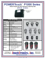
TNC Antenna

(Option)

Not Sealed

P1000-TX4S

P1000-TX6S

With ON/OFF Switch

P1000-TK1

P1000-TK2

P1000-TK4

P1000-TF2-LK

P1000-TF4

P1000-TF6

P1000-TM1

P1000-TM2

P1000-TM4

Receiver can be paired to any transmitter below

TK Sealed Transmitters

TF Sealed Transmitters

TM Transmitters

TX Transmitters

P1000-TF2

P1000-TX2S

RANGE

300 feet typical

Up to 600 feet

OUTPUT

OPTIONAL

6 Relays

7 Relays

INPUT

2 (+12v) A1 & A2

6 (+12v or Ground) B1-B6

FREQUENCY

433 MHz

CODES

Rolling Codes

Secure Encryption

VOLTAGE

12 VDC

24 VDC (Special Order)

CURRENT

5 Amps Max per Output

10 Amp Input - Standard

30 Amp Input - Optional

ANTENNA

OPTIONAL

Fixed - Standard

TNC Whip (shown)

Flex Whip / Roof Mount

Flex Whip / Glass Mount

HARNESS

9" Standard, 14 Pin Connector Standard

6 Pin Connector Optional

2 Pin Connector Optional

BATTERY

All transmitter styles (except TX style)*

   • Coin Style, Lithium, CR2032

   • 100,000 1-second pulses

   • 10 year shelf life

*TX Style - 9V

SYSTEM   SPECIFICATIONS

Model # P1010-R6, P1030-R

TM

Содержание POWERTouch P1000 Series

Страница 1: ...Transmitters P1000 TF2 P1000 TX2S RANGE 300 feet typical Up to 600 feet OUTPUT OPTIONAL 6 Relays 7 Relays INPUT 2 12v A1 A2 6 12v or Ground B1 B6 FREQUENCY 433 MHz CODES Rolling Codes Secure Encryption VOLTAGE 12 VDC 24 VDC Special Order CURRENT 5 Amps Max per Output 10 Amp Input Standard 30 Amp Input Optional ANTENNA OPTIONAL Fixed Standard TNC Whip shown Flex Whip Roof Mount Flex Whip Glass Moun...

Страница 2: ...ITTERS Self Learning Receiver 1 Remove and reconnect power to unit This will place unit into LEARN mode for 5 seconds 2 Press any button on transmitter once Wait 5 seconds and confirm the transmitter has been enrolled by pressing any button and verifying the correct output turned ON OR 1 Remove cover from receiver enclosure 2 Locate LEARN switch small push button style switch located in the corner...

Страница 3: ...GRN BLK PNK BLK VIO BLK 12V A1 12V A2 CHASSIS GROUND 12V LOGIC POWER POWER 5 AMP POWER 5 AMP OUTPUT 1 5 AMP OUTPUT 2 5 AMP OUTPUT 3 5 AMP OUTPUT 4 5 AMP OUTPUT 5 5 AMP OUTPUT 6 5 AMP OUTPUT 7 5 AMP POWER 30 AMP 12v or GND B1 12v or GND B2 12v or GND B3 12v or GND B4 12v or GND B5 12v or GND B6 STANDARD RELAYS 1 4 OPTIONAL RELAYS 5 7 J3 J2 J1 ALL INPUTS B1 B6 ARE LOGIC SIGNALS 1mA ACTIVE WITH EITHE...

Страница 4: ... faire l objet de modifications Déclaration FCC Cet équipement a été testé et déclaré conforme à la section 15 du règlement de la FCC Son fonctionnement est soumis aux conditions suivantes 1 l équipement concerné ne doit pas causer d interférences dangereuses et 2 il doit accepter toute interférence reçue y compris les interférences risquant d engendrer un fonctionnement indésirable Cet équipement...

Отзывы: