Page 180
18. Electrical Characteristics
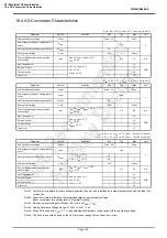
18.4 AD Conversion Characteristics
TMP86PM29BUG
18.4 AD Conversion Characteristics
Note 1: The total error includes all errors except a quantization error, and is defined as a maximum deviation from the ideal con-
version line.
Note 2: Conversion time is different in recommended value by power supply voltage.
About conversion time, please refer to “Register Framing”.
Note 3: Please use input voltage to AIN input Pin in limit of V
AREF
– V
SS
.
Note 4: Analog Reference Voltage Range:
∆
V
AREF
= V
AREF
−
V
SS
Note 5: When AD is used with V
DD
< 2.7 V, the guaranteed temperature range varies with the operating voltage.
Note 6: The A
VDD
pin should be fixed on the V
DD
level even though AD convertor is not used.
(V
SS
= 0.0 V, 4.5 V
≤
V
DD
≤
5.5 V, Topr =
−
40 to 85
°
C)
Parameter
Symbol
Condition
Min
Typ.
Max
Unit
Analog reference voltage
V
AREF
A
VDD
−
1.0
–
A
VDD
V
Power supply voltage of analog control
circuit
A
VDD
V
DD
Analog reference voltage range (Note4)
∆
V
AREF
3.5
–
–
Analog input voltage
V
AIN
V
SS
–
V
AREF
Power supply current of analog refer-
ence voltage
I
REF
V
DD
= A
VDD
= V
AREF
= 5.5 V
V
SS
= 0.0 V
–
0.6
1.0
mA
Non linearity error
V
DD
= A
VDD
= 5.0 V
V
SS
= 0.0 V
V
AREF
= 5.0 V
–
–
±
2
LSB
Zero point error
–
–
±
2
Full scale error
–
–
±
2
Total error
–
–
±
2
(V
SS
= 0.0 V, 2.7 V
≤
V
DD
< 4.5 V, Topr =
−
40 to 85
°
C)
Parameter
Symbol
Condition
Min
Typ.
Max
Unit
Analog reference voltage
V
AREF
A
VDD
−
1.0
–
A
VDD
V
Power supply voltage of analog control
circuit
A
VDD
V
DD
Analog reference voltage range (Note4)
∆
V
AREF
2.5
–
–
Analog input voltage
V
AIN
V
SS
–
V
AREF
Power supply current of analog refer-
ence voltage
I
REF
V
DD
= A
VDD
= V
AREF
= 4.5 V
V
SS
= 0.0 V
–
0.5
0.8
mA
Non linearity error
V
DD
= A
VDD
= 2.7 V
V
SS
= 0.0 V
V
AREF
= 2.7 V
–
–
±
2
LSB
Zero point error
–
–
±
2
Full scale error
–
–
±
2
Total error
–
–
±
2
(V
SS
= 0.0 V, 2.0 V
≤
V
DD
< 2.7 V, Topr =
−
40 to 85
°
C) (Note5)
(V
SS
= 0.0 V, 1.8 V
≤
V
DD
< 2.0 V, Topr =
−
10 to 85
°
C) (Note5)
Parameter
Symbol
Condition
Min
Typ.
Max
Unit
Analog reference voltage
V
AREF
A
VDD
−
0.9
–
A
VDD
V
Power supply voltage of analog control
circuit
A
VDD
V
DD
Analog reference voltage range (Note4)
∆
V
AREF
1.8 V
≤
V
DD
< 2.0 V
1.8
–
–
2.0 V
≤
V
DD
< 2.7 V
2.0
–
–
Analog input voltage
V
AIN
V
SS
–
V
AREF
Power supply current of analog refer-
ence voltage
I
REF
V
DD
= A
VDD
= V
AREF
= 2.7V
V
SS
= 0.0 V
–
0.3
0.5
mA
Non linearity error
V
DD
= A
VDD
= 1.8 V
V
SS
= 0.0 V
V
AREF
= 1.8 V
–
–
±
4
LSB
Zero point error
–
–
±
4
Full scale error
–
–
±
4
Total error
–
–
±
4
Содержание TLCS-870/C Series
Страница 1: ...8 Bit Microcontroller TLCS 870 C Series TMP86PM29BUG ...
Страница 6: ...TMP86PM29BUG ...
Страница 7: ...Revision History Date Revision 2007 10 11 1 First Release 2008 8 29 2 Contents Revised ...
Страница 9: ......
Страница 15: ...vi ...
Страница 19: ...Page 4 1 3 Block Diagram TMP86PM29BUG 1 3 Block Diagram Figure 1 2 Block Diagram ...
Страница 23: ...Page 8 1 4 Pin Names and Functions TMP86PM29BUG ...
Страница 48: ...Page 33 TMP86PM29BUG ...
Страница 49: ...Page 34 2 Operational Description 2 3 Reset Circuit TMP86PM29BUG ...
Страница 61: ...Page 46 3 Interrupt Control Circuit 3 8 External Interrupts TMP86PM29BUG ...
Страница 81: ...Page 66 6 Watchdog Timer WDT 6 3 Address Trap TMP86PM29BUG ...
Страница 135: ...Page 120 10 8 Bit TimerCounter TC5 TC6 10 1 Configuration TMP86PM29BUG ...
Страница 145: ...Page 130 11 Asynchronous Serial interface UART 11 9 Status Flag TMP86PM29BUG ...
Страница 165: ...Page 150 13 10 bit AD Converter ADC 13 6 Precautions about AD Converter TMP86PM29BUG ...
Страница 183: ...Page 168 15 LCD Driver 15 4 Control Method of LCD Driver TMP86PM29BUG ...
Страница 201: ...Page 186 18 Electrical Characteristics 18 9 Handling Precaution TMP86PM29BUG ...
Страница 203: ...Page 188 19 Package Dimensions TMP86PM29BUG ...
Страница 205: ......

