ISDN Interfaces
RBSU/RBSS and TBSU Interface Units
Strata DK I&M 6/00
16-15
ISDN
Inte
rface
s
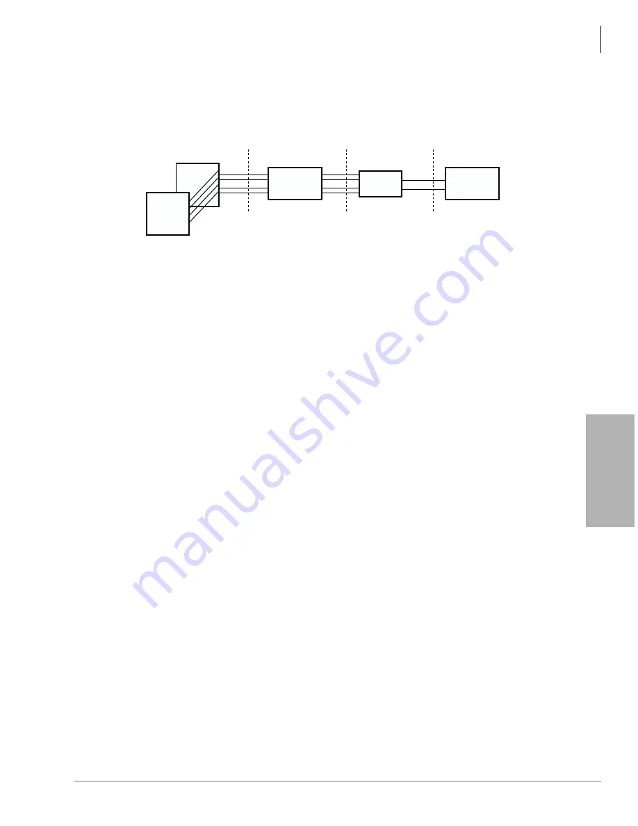
When multiple TE-1 and TA devices are installed on a single TBSU or RBSU/RBSS BRI circuit,
the devices must share, or contend for, that circuit’s two B-channels. That is to say, a maximum of
two simultaneous voice and/or data calls are allowed between both devices connected to the same
BRI circuit. The contention rule for the two BRI B-channels is first come, first serve.
Figure 16-6
TBSU and RBSU/RBSS Interfaces between the S/T Reference Points
Capacity and Cabinet Slot Information
The TBSU can only be installed in the DK40i Base KSU. The RBSU/RBSS can be installed in any
DK40i Expansion Unit slot and any DK424 or DK424i slot except the programming telephone
PDKU or PEKU slot. On DK424 or DK424i, each RBSU and/or RBSS contains two circuits and
each circuit reduces the system capacity by two station ports
and
two CO lines (one port/line per
B-channel). Therefore, if the RBSU PCB is installed, the station port and CO line count will
increment by four ports and four lines at the RBSU cabinet slot.
If the RBSU/RBSS is installed in a DK424 or DK424i slot, the station port and CO line count will
increment by eight station ports and eight lines at the RBSU/RBSS cabinet slot. RBSU and RBSS
PCBs can be installed in any combination so long as the number of RBSU PCBs is the same or
greater than the number of RBSS PCBs. See
, beginning on
for the
maximum BRI circuits allowed.
On DK40i, TBSU and each RBSU and/or RBSS contains two circuits. Each circuit reduces the
system capacity by two station ports or two CO lines. If the BRI circuit is configured as NT, the
circuit assumes two station ports. If the BRI circuit is configured as TE, the circuit assumes two
CO lines.
PS-1 Backup Power Option
The RBSU provides an optional backup power supply, R40S, that will supply backup power to TE
devices in the event of an AC power loss. This power backup option only applies to RBSU or
RBSS circuits that are configured in the NT mode. See
to install the R40S.
Note
The R40S is not available for the TBSU.
Also the DK system must have battery backup to allow the R40S power backup function to
operate. The R40S power supply is an ISDN, PS-1 type power unit which means it supplies power
to TE devices on the RBSU/RBSS transmit and receive wire pairs as shown in
power arrangement is also known as phantom power.
Each of the four circuits on RBSU/RBSS can be connected to share the R40S using option
switches on the PCBs (see
). Before using the R40S as a backup power source, make
RX
TX
DK TBSU or
RBSU/RBSS
NT1
RX
TX
PSTN
RX/TX
U
T
S
BRI
(2-wire)
BRI-TE
(4-wire)
BRI-NT
(4-wire)
3336
S, T, and U are ISDN reference points.
TE = S-type Terminal Equipment
TA = S-type Terminal Adaptor
TE-1
or
TA
1
2
. .
.
TE-1
or
TA
Содержание Strata AirLink DK40i
Страница 22: ...Introduction Related Documents Media xx Strata DK I M 6 00 ...
Страница 48: ...DK14 Installation DK14 Wiring Diagrams 1 26 Strata DK I M 6 00 ...
Страница 220: ...DK424 Installation Remote Cabinet Installation Instructions 5 68 Strata DK I M 6 00 ...
Страница 262: ...DK424i Configuration Primary Reserve Power Cabinet Hardware 6 42 Strata DK I M 6 00 ...
Страница 450: ...Universal Slot PCB Wiring Option Interface PCB Wiring Diagrams 10 42 Strata DK I M 6 00 ...
Страница 592: ...Peripheral Installation Enhanced 911 Service E911 12 84 Strata DK I M 6 00 ...
Страница 616: ...ACD Installation Spectrum Electronic Wall Boards 13 24 Strata DK I M 6 00 ...
Страница 634: ...Fault Finding Fault Isolation Flowcharts 14 18 Strata DK I M 6 00 ...
Страница 704: ...ISDN Interfaces ISDN Disconnect Cause Code 16 54 Strata DK I M 6 00 ...


