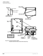
DK424 Installation
RCTUA, RCTUBA/BB, RCTUC/D, RCTUE/F Common Control Units
5-52
Strata DK I&M 6/00
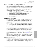
If installing a RCTU PCB perform a processor RAM test using Program 00, part 2. On new RCTU
installations, the RAM test should be run after RCTU initialization and before entering the
customer database.
The following parameters can be specified, through programming, for the RCTU PCB.
Program 00, part 2: RCTU RAM test.
Program 03:
➤
For RCTUA, RCTUBA3, RCTUC/D, RCTUE/F—assign the appropriate slot code for each
PCB: slot code 00 for RCTUA, RCTUBA, RCTUC or RCTUE; slot code 01 for RCTUD and
RCTUF.
➤
Assign the appropriate code for each PCB:
♦
Code 91 – no RRCS
♦
Code 92 – four RRCS circuits
♦
Code 93 – eight RRCS circuits
♦
Code 94 – 12 RRCS circuits
Notes
●
System Power must be cycled or Program 91-2 must be run after Program 03.
●
If there are no options on the RCTU, Program 03 can be skipped and Program 91-1 or 91-
9 can be run instead.
➤
Program *03: For RCTUE/F only. Run program to identify DK424 and DK280 cabinets.
➤
Program 12: Select the seize time of the RRCS circuits.
➤
Program 90, 91, 92: RCTU initialization programs.
DK280 to DK424 Base Cabinet Upgrade Considerations
1. Remove MBJU from the DK424 Base Cabinet motherboard.
2. After installing and initializing the RCTUE/F, run Program *03 to identify the DK280 and
DK424 cabinets.
♦
DK280 Expansion Cabinet slots S_1 to S_6 operate; S_7 and S_8 do not.
♦
DK424 Expansion Cabinets slots S_1 to S_8 operate.
Important!
If installing station and/or CO line PCBs in slots S_7 and S_8, the ports and/or lines
will shift by 4, 8, 16, or 24, depending on the PCBs installed in S_7 and/or S_8.
Toshiba recommends moving the existing 25-pair and modular cables backward, in
order, to the newly installed PCBs to keep the port and CO line numbers matched
with the cable pairs.
Содержание Strata AirLink DK40i
Страница 22: ...Introduction Related Documents Media xx Strata DK I M 6 00 ...
Страница 48: ...DK14 Installation DK14 Wiring Diagrams 1 26 Strata DK I M 6 00 ...
Страница 220: ...DK424 Installation Remote Cabinet Installation Instructions 5 68 Strata DK I M 6 00 ...
Страница 262: ...DK424i Configuration Primary Reserve Power Cabinet Hardware 6 42 Strata DK I M 6 00 ...
Страница 450: ...Universal Slot PCB Wiring Option Interface PCB Wiring Diagrams 10 42 Strata DK I M 6 00 ...
Страница 592: ...Peripheral Installation Enhanced 911 Service E911 12 84 Strata DK I M 6 00 ...
Страница 616: ...ACD Installation Spectrum Electronic Wall Boards 13 24 Strata DK I M 6 00 ...
Страница 634: ...Fault Finding Fault Isolation Flowcharts 14 18 Strata DK I M 6 00 ...
Страница 704: ...ISDN Interfaces ISDN Disconnect Cause Code 16 54 Strata DK I M 6 00 ...

