background image

User’s Manual

4-3

Operating Basics

Using the TOSHIBA Face Recognition

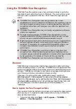
TOSHIBA Face Recognition uses a face verification library to verify the 

face data of users when they log in to Windows. The user can thus avoid 

having to enter a password or the like, which makes the login process 

easier.

Disclaimer

TOSHIBA does not guarantee that the face recognition utility technology 

will be completely secure or error-free. TOSHIBA does not guarantee that 

the face recognition utility will accurately screen out unauthorized users at 

all times. TOSHIBA is not liable for any failure or damage that might arise 

out of the use of the face recognition software or utility.
TOSHIBA, ITS AFFILIATES AND SUPPLIERS SHALL HAVE NO 

RESPONSIBILITY FOR DAMAGE TO OR LOSS OF ANY BUSINESS, 

PROFITS, PROGRAMS, DATA, NETWORK SYSTEMS OR REMOVABLE 

STORAGE MEDIA ARISING OUT OF OR RESULTING FROM THE USE 

OF THE PRODUCT, EVEN IF ADVISED OF THE POSSIBILITY 

THEREOF.

How to register the Face Recognition Data

Take a picture for facial verification purposes, and register the data needed 

when you log in. To register the data needed when you log in, follow the 

steps as described below:
1. To launch this utility, click 

Start

 -> 

All Programs

 -> 

TOSHIBA

 -> 

Utilities

 -> 

Face Recognition

.

TOSHIBA Face Recognition does not guarantee the correct 

identification of a user. Changes to the likeness of a registrant, such as 

hair style changes, wearing a cap, or wearing glasses may effect the 

recognition rates when such changes occur after the registrant had 

registered.

TOSHIBA Face Recognition may incorrectly recognize faces that are 

similar to a registrant.

For high security purposes, TOSHIBA Face Recognition is not a 

suitable substitute for Windows passwords. When security is a high 

priority, use your established Windows passwords to log in. 

Bright background light and/or shadows may prevent a registrant from 

being recognized correctly. In that case, log in using your Windows 

password. If recognition of a registrant fails repeatedly, refer to your 

computer documentation to learn ways to improve recognition 

performance.

TOSHIBA Face Recognition records face data in a log when face 

recognition fails. When transferring ownership or disposing of your 

computer, please uninstall the application or delete all the logs created 

by the application. For details on how to do this, see help file.

TOSHIBA Face Recognition can be used only in Windows 7.

Содержание Satellite L640

Страница 1: ...User s Manual Satellite L640 L640D L645 L645D Satellite Pro L640 L640D L645 L645D Series ...

Страница 2: ...ii Disposing of the computer and the computer s batteries xvii REACH Compliance Statement xviii Following information is only for Turkey xviii Optical disc drive safety instructions xviii Precautions xxi Preface Conventions xxii General Precautions Provide adequate ventilation xxv Creating a computer friendly environment xxv Stress injury xxvi Heat injury xxvi Pressure or impact damage xxvi Mobile...

Страница 3: ...ptional accessories 3 30 Chapter 4 Operating Basics Using the Touch Pad 4 1 Web Camera 4 2 Using the TOSHIBA Face Recognition 4 3 Using optical disc drives 4 6 Writing CD DVD BDs 4 9 TOSHIBA DVD PLAYER 4 21 Using WinDVD BD for TOSHIBA 4 24 Media care 4 26 Sound System 4 26 Modem 4 29 Wireless communications 4 31 LAN 4 34 Computer Handling 4 36 Heat dispersal 4 37 Chapter 5 The Keyboard Typewriter ...

Страница 4: ...eo mode Display controller B 1 Video mode B 1 Appendix C Wireless LAN Card Specifications C 1 Radio Characteristics C 2 Supported Frequency Sub bands C 3 Appendix D Bluetooth wireless technology Interoperability Bluetooth wireless technology and your Health D 3 Regulatory statements D 3 Using Bluetooth Adaptor from TOSHIBA equipment in Japan D 5 Appendix E AC Power Cord and Connectors Certificatio...

Страница 5: ...User s Manual v Satellite L640 L640D L645 L645D Satellite Pro L640 L640D L645 L645D Series Copy Protection G 4 Glossary Index ...

Страница 6: ...t laws in making any reproduction from this manual Disclaimer This manual has been validated and reviewed for accuracy The instructions and descriptions it contains are accurate for the TOSHIBA Satellite L640 L640D L645 L645D Satellite Pro L640 L640D L645 L645D Series Portable Personal Computer at the time of this manual s production However succeeding computers and manuals are subject to change w...

Страница 7: ...radio frequency energy and if not installed and used in accordance with the instructions may cause harmful interference to radio communications However there is no guarantee that interference will not occur in a particular installation If this equipment does cause harmful interference to radio or television reception which can be determined by turning the equipment off and on the user is encourage...

Страница 8: ...European Directives notably Electromagnetic Compatibility Directive 2004 108 EC for the notebook and the electronic accessories including the supplied power adapter the Radio Equipment and Telecommunications Terminal Equipment Directive 1999 5 EC in case of implemented telecommunication accessories and the Low Voltage Directive 2006 95 EC for the supplied power adapter Furthermore the product comp...

Страница 9: ...oduct caused by disturbances generated by other devices or machines in the near surrounding area Therefore TOSHIBA strongly recommend that the electromagnetic compatibility of this product should be suitably tested in all non approved working environments before use In the case of automobiles or aircraft the manufacturer or airline respectively should be asked for permission before use of this pro...

Страница 10: ...ific switch settings or software setup are required for each network please refer to the relevant sections of the user guide for more details The hookflash timed break register recall function is subject to separate national type approvals It has not been tested for conformity to national type regulations and no guarantee of successful operation of that specific function on specific national netwo...

Страница 11: ...located on the device US CXSMM01BRD02D450 The FCC registration number of the modem will be found on either the device which is to be installed or if already installed on the bottom of the computer outside of the main system label The Ringer Equivalence Number REN of the modem which can vary For the REN of your modem refer to your modem s label The modem connects to the telephone line by means of a...

Страница 12: ...u are notified you will be given the opportunity to correct the problem and informed of your right to file a complaint with the FCC In the event repairs are ever needed on your modem they should be performed by TOSHIBA Corporation or an authorized representative of TOSHIBA Corporation Disconnection If you should ever decide to permanently disconnect your modem from its present line please call the...

Страница 13: ... company cause to request the user to disconnect the equipment Users should ensure for their own protection that the electrical ground connections of the power utility telephone lines and internal metallic water pipe systems if present are connected together This precaution may be particularly important in rural areas 2 The user manual of analog equipment must contain the equipment s Ringer Equiva...

Страница 14: ...eing operated in a non compliant manner Consequently there would be no permit in force for this equipment and the Telecoms Act 1991 prescribes a penalty of 12 000 for the connection of non permitted equipment Notes for use of this device in New Zealand The grant of a Telepermit for a device in no way indicates Telecom acceptance of responsibility for the correct operation of that device under all ...

Страница 15: ... ATS0 0 not auto answer ATS6 4 Blind dial delay ATS7 less than 90 Time to wait to carrier after dialing ATS10 less than 150 loss of carrier to hangup delay factory default of 15 recommended ATS11 90 DTMF dialing on off duration 90 ms ATX2 Dial tone detect but not U S A call progress detect When used in the Auto Answer mode the S0 register must be set with a value of 3 or 4 This ensures a A person ...

Страница 16: ...pecifications of these products which might affect compliance with the relevant PTC Specifications The grant of this Telepermit is specific to the above products with the marketing description as stated on the Telepermit label artwork The Telepermit may not be assigned to other parties or other products without Telecom approval A Telepermit artwork for each device is included from which you may pr...

Страница 17: ...e collection of products and batteries you will help to assure the proper disposal of products and batteries and thus help to prevent potential negative consequences for the environment and human health For more detailed information about the collection and recycling programmes available in your country please visit our website http eu computers toshiba europe com or contact your local city office...

Страница 18: ... the use of certain hazardous substances in electrical and electronic equipment The number of possible pixel failures of your display is defined according to ISO 13406 2 standards If the number of pixel failures is less than this standard they will not be counted as defect or failure Battery is a consumption product since the battery time depends on the usage of your computer If the battery can no...

Страница 19: ...User s Manual xix Satellite L640 L640D L645 L645D Satellite Pro L640 L640D L645 L645D Series TEAC DVD Super Multi with Double Layer Recording DV W28S JUNE 24 2007 JUNE 24 2007 ...

Страница 20: ...640D L645 L645D Series Panasonic System Networks DVD Super Multi UJ890 BD Combo UJ141 BD Writer UJ240 HITACHI LG Data Storage Inc DVD Super Multi GT30N GT30F Panasonic System Networks Co Ltd Hitachi LG Data Storage Inc 22 23 KAIGAN 3 CHOME MINATO KU TOKYO 108 0022 JAPAN ...

Страница 21: ...ATAN 3 DONG YEONGTONG GU SUWON CITY GYEONGGI 443 742 KOREA CAUTION This appliance contains a laser system and is classified as a CLASS 1 LASER PRODUCT To use this model properly read the instruction manual carefully and keep this manual for your future reference In case of any trouble with this model please contact your nearest AUTHORIZED service station To prevent direct exposure to the laser bea...

Страница 22: ...r s features components and accessory devices Then read Chapter 1 Getting Started for step by step instructions on setting up your computer If you are an experienced computer user please continue reading the preface to learn how this manual is organized then become acquainted with this manual by browsing through its pages Be sure to read the Special features section in Chapter 3 Hardware Utilities...

Страница 23: ... keys are used hold down the first two and at the same time press the third Display Messages Messages are used in this manual to bring important information to your attention Each type of message is identified as shown below ABC When procedures require an action such as clicking an icon or entering text the icon s name or the text you are to type in is represented in the typeface you see to the le...

Страница 24: ...y This term is defined in this document as follows Start The word Start refers to the button in Windows 7 HDD or Hard disk drive Some models are equipped with a Solid State Drive SSD instead of a hard disk drive In this manual the word HDD or Hard disk drive also refers to the SSD unless otherwise stated ...

Страница 25: ... following Never cover your computer or AC adaptor with any object Never place your computer or AC adaptor near a heat source such as anelectric blanket or heater Never cover or block the air vents including those located at the base of the computer Always operate your computer on a hard flat surface Using your computer on a carpet or other soft material can block the vents Always provide sufficie...

Страница 26: ... reduce physical stress Heat injury Avoid prolonged physical contact with the computer If the computer is used for long periods its surface can become very warm While the temperature will not feel hot to the touch if you maintain physical contact with the computer for a long time for example if you rest the computer on your lap or if you keep your hands on the palm rest your skin might suffer a lo...

Страница 27: ...ion of the computer will not be impaired in any way but it is recommended that a minimum distance of 30cm is maintained between the computer and a mobile phone that is in use Instruction Manual for Safety and Comfort All important information on the safe and proper use of this computer is described in the enclosed Instruction Manual for Safety and Comfort Be sure to read it before using the comput...

Страница 28: ... Personal Computer AC adaptor and power cord 2 pin plug or 3 pin plug Battery pack installed in the computer Documentation Satellite L640 L640D L645 L645D Satellite Pro L640 L640D L645 L645D Series User Information Guide Instruction Manual for Safety and Comfort If any of the items are missing or damaged contact your dealer immediately Software The following Windows operating system and utility so...

Страница 29: ... User s Manual This manual You may not have all the softwares listed above depending on the model you purchased Getting Started This section provides basic information to start using your computer It covers the following topics Connecting the AC adaptor Opening the display Turning on the power Starting up for the first time Turning off the power Restarting the computer System Recovery Options Crea...

Страница 30: ... to 240 volts and 50 or 60 hertz For details on using the AC adaptor to charge the battery pack refer to Chapter 6 Power and Power Up Modes Use a virus check program and make sure it is updated regularly Never format storage media without checking its content formatting destroys all stored data It is a good idea to periodically back up the internal hard disk drive or other main storage device to e...

Страница 31: ...rms to safety rules and regulations in the region the product is bought and should not be used outside this region For use in other regions please buy power cords that conform to safety rules and regulations in the particular region Do not use a 3 pin to 2 pin conversion plug When you connect the AC adaptor to the computer always follow the steps in the exact order as described in the User s Manua...

Страница 32: ...lug 2 Connect the AC adaptor s DC output plug to the DC IN 19V jack on the right of the computer Figure 1 3 Connecting the DC output plug to the computer 3 Plug the power cord into a live wall outlet the Battery and DC IN indicators on the front of the computer should glow Either a 2 pin or 3 pin adaptor cord will be included with the computer depending on the model 1 DC IN 19V jack 2 DC output pl...

Страница 33: ...ng the display panel Opening it vigorously or slamming it shut could damage the computer Be careful not to open the display panel too far as this could put stress on the display panel s hinges and cause damage Do not press or push on the display panel Do not lift the computer by the display panel Do not close the display panel with pens or any other objects left in between the display panel and th...

Страница 34: ... 1 5 Turning on the power Starting up for the first time The Windows 7 Startup Screen will be the first screen displayed when you turn on the power Follow the on screen instructions on each screen in order to properly install the operating system After you turn on the power for the first time do not turn it off until you have set up the operating system Please refer to the section Starting up for ...

Страница 35: ... where you left off Make sure the Hard Disk Drive Optical Disc Drive eSATA indicators are off If you turn off the power while a disk disc is being accessed you may lose data or damage the disk Never turn off the power while an application is running Doing so could cause loss of data Never turn off the power disconnect an external storage device or remove storage media during data read write Doing ...

Страница 36: ...is in Sleep Mode The computer or the memory module could be damaged Do not remove the battery pack while the computer is in Sleep Mode unless the computer is connected to an AC power source Data in memory could be lost When the AC adaptor is connected the computer will go into Sleep Mode according to the settings in the Power Options to access it Start Control Panel System and Security Power Optio...

Страница 37: ... down because of a low battery condition You can return to your previous working environment immediately when you turn on the computer Saves power by shutting down the system when the computer receives no input or hardware access for the time period set by the System Hibernate feature Allows the use of the panel power off feature When the computer is in Sleep Mode the power indicator will blink am...

Страница 38: ...tion Mode the computer will take a moment to save the current data in memory to the hard disk drive During this time the Hard Disk Drive indicator will glow After you turn off the computer and the content of memory has been saved to the hard disk drive turn off the power to any peripheral devices Restarting the computer Certain conditions require that you reset the computer for example if You chan...

Страница 39: ...nostics or restore the system See the Windows Help and Support content for more information about Startup Repair The System Recovery Options can also be run manually to repair problems The procedure is as follows Follow the instructions shown on the on screen menu 1 Turn off the computer 2 While holding the F8 key turn on the computer 3 The Advanced Boot Options menu will be displayed Use the arro...

Страница 40: ...daptor when you create Recovery Media Be sure to close all other software programs except the Recovery Media Creator Do not run software such as screen savers which can put a heavy load on the CPU Operate the computer at full power Do not use power saving features Do not write to the media when the virus check software is running Wait for it to finish then disable virus detection programs includin...

Страница 41: ...talled software from your created Recovery Media If the pre installed files are damaged you are able to either use the Recovery Media you have created or the hard disk drive recovery process to restore the computer to the state it was in when you originally received it To perform this restoration follow the steps below When the sound mute feature has been activated by pressing the FN ESC key be su...

Страница 42: ...from the menu according to your actual recovery media Please refer to the Boot Priority section in Chapter 7 HW Setup for further information 4 A menu will be displayed from which you should follow the on screen instructions When you reinstall the Windows operating system the hard disk will be reformatted and all data will be lost When drivers utilities are installed you can setup the respective d...

Страница 43: ...he following figure shows the computer s front with its display panel in the closed position Figure 2 1 Front of the computer with display panel closed Legal Footnote Non applicable Icons For more information regarding Non applicable Icons please refer to the Legal Footnotes section in Appendix G Please handle your computer carefully to avoid scratching or damaging the surface 1 System indicators ...

Страница 44: ...re Utilities and Options Keep foreign metal objects such as screws staples and paper clips out of the Bridge media slot Foreign metal objects can create a short circuit which can cause damage and fire possibly resulting in serious injury 1 Security lock slot 6 eSATA USB combo port 2 Modem jack 7 Universal Serial Bus USB 2 0 port 3 Cooling vents 8 Microphone jack 4 LAN jack 9 Headphone jack 5 HDMI ...

Страница 45: ...p foreign metal objects such as screws staples and paper clips out of the cooling vents Foreign metal objects can create a short circuit which can cause damage and fire possibly resulting in serious injury LAN jack This jack lets you connect to a LAN The adaptor has built in support for Ethernet LAN 10 megabits per second 10BASE T Fast Ethernet LAN 100 megabits per second 100BASE TX Some models ar...

Страница 46: ...an cause damage and fire possibly resulting in serious injury Please note that it is not possible to confirm the operation of all functions of all USB devices that are available In view of this it may be noted that some functions associated with a specific device might not operate properly Microphone jack A 3 5 mm mini microphone jack enables connection of a three conductor mini jack for monaural ...

Страница 47: ...s to this jack in order to power the computer and charge its internal batteries Please note that you should only use the model of AC adaptor supplied with the computer at the time of purchase using the wrong AC adaptor can cause damage to the computer 1 Battery pack 1 Battery pack The battery pack provides power to the computer when the AC adaptor is not connected For more detailed information on ...

Страница 48: ...ery lock Slide the battery lock to release the battery pack ready for removal Battery release latch Slide and hold this latch into its Unlock position in order to release the battery pack for removal For more detailed information on removing the battery pack please refer to Chapter 6 Power and Power Up Modes Memory module slot The memory module slot allows for the installation replacement and remo...

Страница 49: ...lay panel open Provided with some models Product appearance depends on the model you purchased 1 Microphone 9 Touch Pad 2 Web Camera LED 10 Touch Pad control buttons 3 Web Camera 11 Bluetooth antenna Not shown 4 Wireless LAN and Wireless WAN antennas Not shown 12 Stereo speaker Left 5 Display hinges 13 Display hinges 6 Stereo speaker Right 14 Power button 7 Keyboard 15 LCD Sensor switch Not shown ...

Страница 50: ...using specialized applications Some models are equipped with a Web Camera Please refer to the Web Camera section in Chapter 4 Operating Basics Wireless LAN antennas Some computers in this series are equipped with the Wireless LAN antennas Wireless WAN antennas Some computers in this series are equipped with the Wireless WAN antennas Display hinges The display hinges allow the display panel to be p...

Страница 51: ...ou close the display panel the computer enters Hibernation Mode and shuts itself down and then when you next open the display the computer will automatically start up and return you to the application you were previously working on You can specify within the Power Options To access it click Start Control Panel System and Security Power Options Do not put any magnetic objects close to this switch a...

Страница 52: ...e the system is shutting down and while it remains turned off Battery The Battery indicator shows the condition of the battery s charge white indicates the battery is fully charged amber indicates the battery is charging and flashing amber indicates a low battery condition Please refer to Chapter 6 Power and Power Up Modes for more information on this feature Hard Disk Drive Optical Disc Drive eSA...

Страница 53: ...ptical disc operation When the computer is accessing an optical disc an indicator on the drive glows For information on loading and unloading discs refer to the Using optical disc drives section in Chapter 4 Operating Basics Region codes for DVD drives and media DVD Super Multi drives and their associated media are manufactured according to the specifications of six marketing regions When you purc...

Страница 54: ...Chapter 4 Operating Basics CDs CD R discs can be written only once The recorded data cannot be erased or changed CD RW discs including multi speed CD RW discs high speed CD RW discs and ultra speed CD RW discs can be recorded more than once DVDs DVD R DVD R DVD R Dual Layer and DVD R Double Layer discs can be written only once The recorded data cannot be erased or changed DVD RW DVD RW and DVD RAM...

Страница 55: ...is slower at the center of a disc and faster at the outer edge BD read 6 speed maximum BD DL read 6 speed maximum BD R write 6 speed maximum BD R DL write 4 speed maximum BD RE write 2 speed maximum BD RE DL write 2 speed maximum DVD read 8 speed maximum DVD R write 8 speed maximum DVD R DL write 4 speed maximum DVD RW write 6 speed maximum DVD R write 8 speed maximum DVD R DL write 4 speed maximu...

Страница 56: ...d 8 speed maximum DVD R write 8 speed maximum DVD R DL write 4 speed maximum DVD RW write 6 speed maximum DVD R write 8 speed maximum DVD R DL write 4 speed maximum DVD RW write 8 speed maximum DVD RAM write 5 speed maximum CD read 24 speed maximum CD R write 24 speed maximum CD RW write 16 speed maximum Ultra speed media The read speed is slower at the center of a disc and faster at the outer edg...

Страница 57: ...ion either a 2 pin or 3 pin adaptor power lead will be bundled with the computer Do not use a 3 pin to 2 pin conversion plug The supplied power cord conforms to safety rules and regulations in the region the product is bought and should not be used outside of this region In order to use the adaptor computer in other regions you should please buy a power cord that conforms to the safety rules and r...

Страница 58: ...hased Processor CPU Your computer is equipped with one processor and processor type varies depending on model To check which type of processor is included in your model open the TOSHIBA PC Diagnostic Tool Utility by clicking Start All Programs TOSHIBA Utilities PC Diagnostic Tool Legal Footnote CPU For more information on the CPU please refer to the Legal Footnotes section in Appendix G ...

Страница 59: ... s hardware specifications This is correct because the operating system usually displays the available memory instead of the physical memory RAM built into the computer Various system components like the video adapter s GPU and PCI devices like Wireless LAN etc require their own memory space Since a 32 bit operating system cannot address more than 4 GB of memory these system resources overlap the ...

Страница 60: ...a range of AC voltages from 100 to 240 volts however you should note that the output current varies among different models Using the wrong adaptor can damage your computer Refer to the AC adaptor section in Chapter 2 The Grand Tour Hard disk drive or Solid state drive This computer is equipped with one of the following hard disk drive HDD types The capacity of each hard disk drive model is differe...

Страница 61: ...ntel Graphics and Media Control Panel In this manual the word HDD or Hard disk drive also refers to the SSD unless otherwise stated SSD is a large capacity storage media which uses Solid State Memory in place of a magnetic disk of the hard disk Under certain unusual conditions of prolonged non use and or exposure to high temperatures the SSD may be vulnerable to data retention errors Legal Footnot...

Страница 62: ...g picture contrast on the internal LCD This feature can be used if the computer is running under battery mode using the internal LCD display only The Vari Bright feature can be enabled in the Catalyst Control Center To access this center go to Start All Programs Catalyst Control Center CCC Advanced In this control center 1 Click Graphics at the upper left and then select PowerPlay from the drop do...

Страница 63: ...refer to the Web Camera section in Chapter 4 Operating Basics Modem The integrated modem provides capability for data and fax communications that support the V 90 V 92 standards and includes a modem jack for connection to the telephone line Please note that both the V 90 and V 92 standards are only supported in the USA Canada United Kingdom France Germany and Australia only the V 90 standard is su...

Страница 64: ...e with other wireless LAN systems based on Direct Sequence Spread Spectrum Orthogonal Frequency Division Multiplexing radio technology that complies with the IEEE 802 11 Standard Legal Footnote Wireless LAN For more information regarding Wireless LAN please refer to the Legal Footnotes section in Appendix G Hot keys Hot keys are specific key combinations that let you quickly change the system conf...

Страница 65: ...Battery save mode 1 This feature lets you configure the computer in order to save battery power This can be specified in the Power Options Panel power on off 1 This feature automatically turns power to the computer off when the display panel is closed and turns it back on when the display panel is opened This can be specified in the Power Options Low battery automatic Hibernation Mode 1 When batte...

Страница 66: ...details Sleep Mode If you have to interrupt your work you can use this feature to allow you to turn off power to the computer without exiting from your software Data is maintained in the computer s main memory so that when you next turn on the power you can continue working right where you left off USB Wakeup function This function restores the computer from Sleep Mode depending on the external de...

Страница 67: ...o customize your hardware settings according to the way you work with the computer and the peripherals you use TOSHIBA Accessibility The TOSHIBA Accessibility utility provides support to movement impaired users when they need to use the TOSHIBA Hot key functions In use the utility allows you to make the FN key sticky that is you can press it once release it and they press one of the Function keys ...

Страница 68: ...figFree is a suite of utilities that improve the ease and control of communication devices and network connections help in the identification of communication problems and allow the creation of profiles if you need to switch between different locations and communication networks To access this utility click Start All Programs TOSHIBA ConfigFree TOSHIBA Disc Creator You can create CDs and DVDs in a...

Страница 69: ...o access the utility click Start All Programs TOSHIBA Utilities HDD SSD Alert TOSHIBA Service Station This application allows your computer to automatically search for TOSHIBA software updates or other alerts from TOSHIBA that are specific to your computer system and its programs When enabled this application periodically transmits to our servers a limited amount of system information which will b...

Страница 70: ... on the label surface of Labelflash compatible media without using a printer This application is the feature of DVD MovieFactory in some models For more information please refer to the When Using Corel DVD MovieFactory for TOSHIBA section in Chapter 4 Operating Basics Labelflash features cannot be used in models that do not have a DVD Super Multi BD Combo BD Writer drive with Labelflash In order t...

Страница 71: ...s utility click Start All Programs TOSHIBA Utilities eco Utility TOSHIBA Bulletin Board Bulletin Board is a convenient place to pin things to visually organize in a fun and creative way Simply drag and drop your favorite pictures files or notes to pin them on the Board You can use it to create thumbnail shortcuts reminders to do list and so on according to your personal style To access this utilit...

Страница 72: ... control your music pictures and videos by streaming content to any compatible device in your home To access this utility click Start All Programs TOSHIBA TOSHIBA Media Controller TOSHIBA Media Controller For more information please refer to the TOSHIBA Media Controller Help TOSHIBA Speech System The TOSHIBA Speech System consists of a voice composition application text to speech that analyzes doc...

Страница 73: ...ory Stick Duo is not compatible with the Bridge media slot Do not insert Memory Stick Duo into the slot or you may not be able to remove it Data may be lost or damaged if you use any memory media other than those supported This Bridge media slot supports the following memory media Secure Digital SD Card SD memory card SDHC memory card SDXC memory card miniSD Card microSD Card Memory Stick Memory S...

Страница 74: ...maximum capacity of SD memory cards is 2GB The maximum capacity of SDHC memory cards is 32GB The maximum capacity of SDXC memory cards is 64GB Memory media format New media cards are formatted according to specific standards If you wish to reformat a media card be sure to do so with a device that uses media cards Formatting an SD SDHC SDXC memory card SD SDHC SDXC memory cards are sold already for...

Страница 75: ...cards have a limited lifespan so it is important to backup important data Do not write to a card if the battery power is low Low power could affect writing accuracy Do not remove a card while read write is in progress About the write protect The following memory media have a function for protect SD Card SD memory card SDHC memory card SDXC memory card Memory Stick Memory Stick Memory Stick PRO Mul...

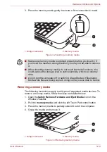
Страница 76: ... control button 3 Press the memory media to partially extend it out of the computer 4 Grasp the media and remove it Figure 3 3 Removing memory media 1 Bridge media slot 2 Memory media 1 2 Make sure memory media is oriented properly before you insert it If you insert the media in wrong direction you may not be able to remove it When inserting memory media do not touch the metal contacts You could e...

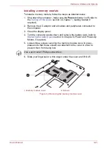
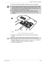
Страница 77: ... static electricity When installing or removing a memory module you must ensure that you do not touch any other internal areas of the computer Insert the two memory modules into Slot A and Slot B respectively The computer will operate in dual channel mode You can access the inserted memory modules efficiently in dual channel Use a point size 0 Phillips screwdriver to remove and fasten the screws t...

Страница 78: ...d to the computer 3 Close the display panel 4 Turn the computer upside down and remove the battery pack refer to Replacing the battery pack section in Chapter 6 Power and Power Up Modes if required 5 Loosen three screws securing the memory module cover in place please note that those screws are attached to the cover in order to prevent them from being lost 6 Slide your fingernail or a thin object ...

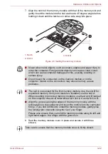
Страница 79: ...h the connectors on the memory module or on the computer Debris on the connectors may cause memory access problems The slot A is reserved for the first memory module Use the slot B for expanded memory If only one module is installed use the slot A When inserting or removing memory modules use the A and B marked on the computer chassis to determine which slot is A and which is B Align the grooves a...

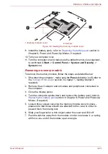
Страница 80: ...fer to the Turning off the power section in Chapter 1 Getting Started if required 2 Remove the AC adaptor and all cables and peripherals connected to the computer 3 Close the display panel 4 Turn the computer upside down and remove the battery pack refer to Replacing the battery pack section in Chapter 6 Power and Power Up Modes if required 5 Loosen three screws securing the memory module cover in...

Страница 81: ...wer and Power Up Modes if required 11 Turn your computer over If you use the computer for a long time the memory modules and the circuits locating close to the memory modules will become hot In this case let them cool to room temperature before you replace them Or you will get burnt if you touch any of them Do not touch the connectors on the memory module or on the computer Debris on the connector...

Страница 82: ... on the correct monitor you should consider using the FN F5 hot key to change the display settings if you then disconnect the external monitor before you turn the computer s power off be sure to press FN F5 hot key again to switch to the internal display Please refer to Chapter 5 The Keyboard for further details on using hot keys to change the display setting When displaying desktop at external an...

Страница 83: ...ke sure the connector is properly aligned with the socket Do not try to force the connection doing so can damage the connecting pins 1 eSATA cable 2 eSATA USB combo port 1 2 A connected eSATA device may not be recognized if it is connected to the computer s eSATA USB combo port while the computer is in Sleep Mode or Hibernation Mode If this occurs disconnect the eSATA device and then reconnect the...

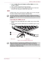
Страница 84: ...ing the HDMI out port 1 Plug one end of the HDMI cable into the HDMI out port of the HDMI device 2 Plug the other end of the HDMI cable into the HDMI out port on your computer Figure 3 10 Connecting the HDMI out port As the port operation of all HDMI High Definition Multimedia Interface monitors have not been confirmed some HDMI monitors may not function properly 1 HDMI out port 2 HDMI cable 1 2 W...

Страница 85: ...nds before you replug the HDMI cable again When you connect a television or external monitor to the HDMI port and you connect the television external monitor or external sound device to another port When you change the display output or Unplug re plug the HDMI cable The sound output device and the display output device maybe changed automatically by the system Be sure to use the FN F5 HotKey to se...

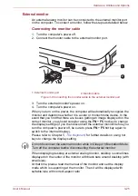
Страница 86: ...ct The methods used for attaching security cables differ from product to product Please refer to the instructions for the product you are using for more information Connecting the security lock In order to connect a security cable to the computer follow the steps as detailed below 1 Turn the computer so its left side faces you 2 Align the security cable with the lock slot and secure it in place Fi...

Страница 87: ...dule DDR3 1066 1333 1600 can easily be installed in the computer Universal AC Adaptor If you frequently use your computer at more than one site it may be convenient to purchase an additional AC adaptor to be kept at each site in order to remove the need to always carry the adaptor with you Battery Pack An additional battery pack can be purchased for use as either a spare or replacement Please refe...

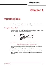
Страница 88: ...inter to go Figure 4 1 Touch Pad and Touch Pad control buttons Press Touch Pad ON OFF button could enable or disable the Touch Pad function The two buttons below the Touch Pad are used like the buttons on a standard mouse press the left button to select a menu item or to manipulate text or graphics designated by the pointer and press the right button to display a menu or other function depending o...

Страница 89: ...lication Help for details Figure 4 2 Web Camera You can also tap the Touch Pad to perform functions similar to those of the left button on a standard mouse Click Tap once Double click Tap twice Drag and drop Tap to select the item s you want to move leave your finger on the Touch Pad after the second tap and then move the item s to their new destination 1 Web Camera 3 Microphone 2 Web Camera LED 2...

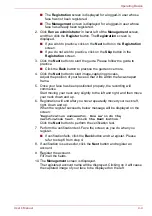
Страница 90: ...ed when you log in follow the steps as described below 1 To launch this utility click Start All Programs TOSHIBA Utilities Face Recognition TOSHIBA Face Recognition does not guarantee the correct identification of a user Changes to the likeness of a registrant such as hair style changes wearing a cap or wearing glasses may effect the recognition rates when such changes occur after the registrant h...

Страница 91: ... within the face shaped frame 5 Once your face has been positioned properly the recording will commence Start moving your neck very slightly to the left and right and then move your neck down and up 6 Registration will end after you have repeatedly moved your neck left right down and up When the register succeeds below message will be displayed on the screen Registration successful Now we ll do th...

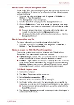
Страница 92: ...rams TOSHIBA Utilities Face Recognition Help Windows Logon via TOSHIBA Face Recognition This section explains how to login to Windows with TOSHIBA Face Recognition Two authentication modes are provided 1 N Mode Login screen If the face authentication tile is selected by default you can log in without using the keyboard or mouse 1 1 Mode Login screen This mode is essentially the same as AUTO mode b...

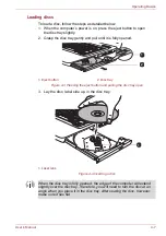
Страница 93: ...reen 8 The Windows Welcome screen will be displayed and will be logged in automatically to Windows If authentication was successful but an authentication error subsequently occurred during the login to Windows you will be asked to provide your account information Using optical disc drives The full size drive provides high performance execution of CD DVD BD based programs You can run either 12 cm 4...

Страница 94: ...lly opened Figure 4 3 Pressing the eject button and pulling the disc tray open 3 Lay the disc label side up in the disc tray Figure 4 4 Inserting a disc 1 Eject button 2 Disc tray 1 Laser lens 1 2 1 When the disc tray is fully opened the edge of the computer will extend slightly over the disc tray Therefore you will need to turn the disc at an angle when you place it in the disc tray After seating...

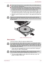
Страница 95: ...ny portion of its surrounding casing as this could cause misalignment Prevent foreign objects from entering the drive Check the surface of the disc tray especially the area behind the front edge of the disc tray to make sure there are no such objects before closing the drive If the disc is not seated properly when the disc tray is closed the disc might be damaged Also the disc tray might not open ...

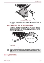
Страница 96: ...sc tray when the computer power is off If the power is off you can open the disc tray by inserting a slender object about 15 mm such as a straightened paper clip into the eject hole near the eject button Figure 4 7 Manual release with the eject hole Writing CD DVD BDs 1 Eject hole Diameter 1mm 1 Turn off the power before you use the eject hole If the disc is spinning when you open the disc tray th...

Страница 97: ... find that the DVD Super Multi drive or BD Writer BD Combo drive may not function properly and you may fail to write or rewrite information successfully this may cause you to either lose data or incur other damage to the drive or media Some models in this series are equipped with a BD Writer BD Combo drive which can write CD DVD BDs Some models in this series are equipped with a DVD Super Multi dr...

Страница 98: ...riting errors due to disc quality or problems with hardware devices In view of this it is good practice to make two or more copies of important data in case of any undesired change or loss of the recorded contents Before writing or rewriting with the BD Writer drive Based on TOSHIBA s limited compatibility testing we suggest the following manufacturers of CD R CD RW DVD R DVD R Dual Layer DVD RW D...

Страница 99: ... RW DVD Specifications for Recordable Disc for Version 1 1 or version 1 2 Victor Company of Japan Ltd JVC for 4x and 6x speed media DVD RW MITSUBISHI KAGAKU MEDIA CO LTD for 4x and 8x speed media DVD RAM DVD Specifications for DVD RAM Disc for Version 2 0 Version 2 1 or Version 2 2 Panasonic Corporation for 3x and 5x speed media Hitachi Maxell Ltd for 3x and 5x speed media BD R Panasonic Corporati...

Страница 100: ...tachi Maxell Ltd CD RW Multi Speed and High Speed MITSUBISHI KAGAKU MEDIA CO LTD CD RW Ultra Speed MITSUBISHI KAGAKU MEDIA CO LTD DVD R DVD Specifications for Recordable Disc for General Version 2 0 TAIYO YUDEN Co Ltd for 4x 8x and 16x speed media DVD R Dual Layer MITSUBISHI KAGAKU MEDIA CO LTD for 4x and 8x speed media DVD R for Labelflash FUJIFILM CORPORATION for 16x speed media DVD R MITSUBISHI...

Страница 101: ... Version 2 0 Version 2 1 or Version 2 2 Panasonic Corporation for 3x and 5x speed media Hitachi Maxell Ltd for 3x and 5x speed media CD R TAIYO YUDEN CO Ltd MITSUBISHI KAGAKU MEDIA CO LTD Hitachi Maxell Ltd CD RW Multi Speed and High Speed MITSUBISHI KAGAKU MEDIA CO LTD CD RW Ultra Speed MITSUBISHI KAGAKU MEDIA CO LTD DVD R DVD Specifications for Recordable Disc for General Version 2 0 TAIYO YUDEN...

Страница 102: ...DVD RW DVD R DVD R Double Layer or DVD RW discs Data written to a CD R DVD R DVD R Dual Layer DVD R or DVD R Double Layer discs cannot be deleted either in whole or in part DVD R Double Layer MITSUBISHI KAGAKU MEDIA CO LTD for 2 4x and 8x speed media DVD R for Labelflash FUJIFILM CORPORATION for 16x speed media DVD RW DVD Specifications for Recordable Disc for Version 1 1 or version 1 2 Victor Com...

Страница 103: ...his instance writing is finished if you can eject the DVD RAM media Be sure to close all other software programs except for the writing software itself Do not run software such as a screen saver which can put a heavy load on the processor Operate the computer at its full power settings do not use any power saving features Do not write information while virus checking software is running instead wa...

Страница 104: ...e writing is completed if you can remove an optical media on the DVD Super Multi drive or BD Writer BD Combo drive If the media is of poor quality or is dirty or damaged writing or rewriting errors may occur Set the computer on a level surface and avoid places subject to vibration such as airplanes trains or cars In addition do not use the computer on an unstable surface such as a stand Keep mobil...

Страница 105: ... need Service Pack 2 In addition to this some DVD ROM and DVD ROM CD R RW drives cannot read this added data regardless of the operating system TOSHIBA Disc Creator does not support recording to DVD RAM discs to achieve this you should use Windows Explorer or another similar utility When you back up a DVD disc be sure that the source drive supports recording to DVD R DVD R Dual Layer DVD RW DVD R ...

Страница 106: ...lick Print How to make a DVD Video Simplified steps for making a DVD Video from adding video source 1 Click Start All Programs DVD MovieFactory for TOSHIBA DVD MovieFactory Launcher to launch DVD MovieFactory 2 Insert a DVD R DVD R DVD RW or DVD RW disc in Burner 3 Click Create Video Disc New Project and choose your Project format 4 Add source from HDD by clicking Add Video files button to invoke ...

Страница 107: ...ieFactory Operate the computer at Full Power Do not use power saving features While you are editing DVD you can display preview However if another application is running The preview might not display properly DVD MovieFactory cannot edit or play copy protected content Do not enter Sleep or Hibernation Mode while using DVD MovieFactory Do not operate DVD MovieFactory immediately after turning on th...

Страница 108: ...OSHIBA DVD PLAYER When playing your recorded Blu ray Disc on your computer please use the WinDVD BD for TOSHIBA If you use an over used rewritable disc the full formatting might be locked Please use a brand new disc Some DVD ROM drives for personal computers or other DVD players may not be able to read DVD R R RW RW RAM discs Some BD Writer BD Combo drives for personal computers or other Blu ray d...

Страница 109: ...ode or shutdown while using TOSHIBA DVD PLAYER Do not configure the Display automatic power off function to run while the TOSHIBA DVD PLAYER is running Do not switch to Hibernation or Sleep Mode when running the TOSHIBA DVD PLAYER Do not lock the computer using the Windows logo L keys or the FN F1 keys when running the TOSHIBA DVD PLAYER Do not change Windows Users while TOSHIBA DVD PLAYER is runn...

Страница 110: ...ternal display or TV change the display device before playing DVD Video cannot be displayed simultaneously in clone mode on both the computer s display panel and an external display Do not change the display device while running the TOSHIBA DVD PLAYER Do not change the screen resolution while running the TOSHIBA DVD PLAYER Starting TOSHIBA DVD PLAYER Use the following procedure to start TOSHIBA DV...

Страница 111: ...A Notes on use WinDVD BD for TOSHIBA is for Blu ray Disc playback only DVD playback is not supported Please use TOSHIBA DVD PLAYER for DVD playback Playback of high bit rate content may cause frame dropping audio skipping or decrease in computer performance Close all other applications before playing back Blu ray Disc Do not open any other applications or carry out any other operations during Blu ...

Страница 112: ... may not work depending on the contents or network situation Region codes for BD drives and media BD drives and their associated media are manufactured according to the specifications of three marketing regions Region codes can be set from WinDVD BD Region tab in Setup dialogue When you purchase BD Video make sure it matches your drive otherwise it will not play properly To playback video on an ex...

Страница 113: ...ata stored on it 1 Store your CD DVD BDs in the containers they originally came in to protect them and keep them clean 2 Do not bend the CD DVD BDs 3 Do not write on apply a sticker to or otherwise mar the surface of the CD DVD BD that contains the data 4 Hold the CD DVD BD by its outside edge or the edge on the center hole any fingerprints on the surface of the disc can prevent the drive from pro...

Страница 114: ...ion explains how to select an existing scheme or save one you have modified To launch the configuration dialog window for system sounds follow the steps below 1 Right click the Speaker icon on the taskbar 2 Select Sounds from the menu SmartAudio Your computer contains SmartAudio a powerful program that allows you to configure your audio software to enhance and personalize your listening experience...

Страница 115: ...ct Playback Devices from the sub menu 2 Select Speakers and click Properties 3 Click the Dolby tab Adjusting Microphone Level Follow the steps below to change the microphone recording level 1 Right click on the speaker icon on the Taskbar and select Recording devices from the sub menu 2 Select Microphone and click Properties 3 On the Levels tab move the Microphone slider to increase or decrease th...

Страница 116: ... 2 Click Phone and Modem 3 In the Dialing Rules tab select a location from the Locations list and then click Edit Connection to any communication line other than an analog phone line could cause a computer system failure Connect the built in modem only to ordinary analog phone lines Never connect the built in modem to a digital line ISDN Never connect the built in modem to the digital connector on...

Страница 117: ...orted local settings of the modem will default to the United States Connection to any communication line other than an analog phone line could cause a computer system failure Connect the built in modem only to ordinary analog phone lines Never connect the built in modem to a digital line ISDN Never connect the built in modem to the digital connector on a public telephone or to a digital private br...

Страница 118: ...unication is periodically interrupted Skips or jumps may be noted in sound Do not use the Wireless LAN Wi Fi or Bluetooth functionalities near a microwave oven or in areas subject to radio interference or magnetic fields Interference from a microwave oven or other source can disrupt Wi Fi or Bluetooth operation Turn all wireless functionalities off when near a person who may have a cardiac pacemak...

Страница 119: ...using a wireless connection If this occurs the outsider may illegally access your system eavesdrop or cause the loss or destruction of stored data TOSHIBA is not liable for the loss of data due to eavesdropping or illegal access through the wireless LAN and the damage thereof Bluetooth wireless technology Bluetooth wireless technology eliminates the need for cables such as desktop computers betwee...

Страница 120: ... below with further details being contained with the electronic help files supplied with the software Release Notes related to the Bluetooth Stack for Windows by TOSHIBA 1 Fax application software Please be aware that there is some fax application software that you cannot use on this Bluetooth Stack 2 Multi user considerations The use of Bluetooth is not supported in a multi user environment This ...

Страница 121: ...AN 1000 megabits per second 1000BASE T This section describes how to connect disconnect to a LAN LAN cable types Indicator status Indication Indicator off The wireless communication function is off no wireless functionality is available Indicator glows The wireless communication function is on Except for the stopped device by the software switch all the wireless communications functions can output...

Страница 122: ...the computer 2 Plug one end of the cable into the LAN jack Press gently until you hear the latch click into place Figure 4 10 Connecting the LAN cable 3 Plug the other end of the cable into a LAN hub connector or router Check with your LAN administrator and hardware or software vendor before using or configuring a network connection Connect the AC adaptor before connecting the LAN cable The AC ada...

Страница 123: ...cope of any damage Clean the plastics of the computer using a slightly water dampened cloth You can clean the display screen by spraying a small amount of glass cleaner onto a soft clean cloth and then wiping the screen gently with the cloth Moving the computer While the computer is designed for flexible day to day usage you should exercise a few simple precautions when moving it in order to help ...

Страница 124: ...g the processor is equipped with an internal temperature sensor which activates a cooling fan or lowers the processing speed if the computer s internal temperature rises to a certain level You are able to select whether to control this temperature by either turning on the fan first then if necessary lowering the processor speed or by lowering the processor speed first then if necessary turning on ...

Страница 125: ...d special symbols that appear on the screen However there are some differences between using a typewriter and using a computer keyboard Letters and numbers produced in computer text vary in width Spaces which are created by a space character may also vary depending on line justification and other factors The lowercase l el and the number 1 one together with the uppercase O oh and the 0 zero are no...

Страница 126: ...unction is unique to TOSHIBA computers and is used in combination with other keys to form soft keys Soft keys are key combinations that enable disable or configure specific features Emulating keys on an enhanced keyboard Figure 5 1 A 104 key enhanced keyboard layout This computer s keyboard is designed to provide all the features of the 104 key enhanced keyboard Since the keyboard is smaller and h...

Страница 127: ...t the power on default for both settings is off Press FN F12 ScrLock to lock the cursor on a specific line The power on default is off Hot keys Hot keys pressing FN a function or ESC key let you enable or disable certain features of the computer Mute Pressing FN ESC turns the volume on and off Lock Pressing FN F1 enters Lock computer mode To restore your desktop you need to log on again Power Plan...

Страница 128: ...ches the active wireless devices Touch Pad Pressing FN F9 enables or disables the Touch Pad function Zoom Pressing FN Space changes the display resolution TOSHIBA Zooming Utility reduce Pressing FN 1 reduces the icon size on the desktop or the font sizes within one of the supported application windows To use a simultaneous mode you must set the resolution of the internal display panel to match the...

Страница 129: ...keyboard provides two keys that have special functions in Windows the Windows Start Button key activates the Start menu while the application key has the same function as the secondary right mouse button This key activates the Windows Start menu This key has the same function as the secondary right mouse button Keypad overlay Your computer s keyboard does not have a separate numeric keypad but inc...

Страница 130: ...rlay Temporarily using normal keyboard overlay on While using the overlay you can temporarily access the normal keyboard functions without having to turn the overlay off 1 Hold down FN key and press any other key this key will operate as if the overlay were off 2 Type upper case characters by holding down FN SHIFT and pressing a character key 3 Release FN key to continue using the selected overlay...

Страница 131: ... temporarily to Numeric Mode by also pressing a SHIFT key Generating ASCII characters Not all ASCII characters can be generated using normal keyboard operation but you are able to generate these characters using their specific ASCII codes 1 Hold down ALT key 2 Using the numeric keypad type the ASCII code of the character you require 3 Release ALT the ASCII character will appear on the display scre...

Страница 132: ... and battery charge status are affected by different power conditions including whether an AC adaptor is connected whether a battery pack is installed and what the charge level is for that battery Table 6 1 Power conditions Power on Power off no operation AC adaptor connected Battery fully charged Operates No charge LED Battery white DC IN white No charge LED Battery white DC IN white Battery part...

Страница 133: ...below low battery trigger point Operates LED Battery flashes amber DC IN off Battery charge is exhausted Computer shuts down No battery installed No operation LED Battery off DC IN off Flashing amber The battery charge is low the AC adaptor must be connected in order to recharge the battery Amber Indicates the AC adaptor is connected and the battery is charging White Indicates the AC adaptor is co...

Страница 134: ...the battery pack save your data and shut down the computer or place the computer into Hibernation Mode Please be aware that when placing the computer into Hibernation Mode the contents of memory will be saved to the hard disk drive although for safety sake it is best to also save your data manually White Indicates the AC adaptor is connected and is correctly supplying power to the computer Flashin...

Страница 135: ...e the Real Time Clock settings by turning the computer on while pressing the F2 key and then release the F2 key when the TOSHIBA Leading Innovation screen appears Please refer to Chapter 8 Troubleshooting for further information Care and use of the battery pack This section provides the important safety precautions in order to handle your battery pack properly Refer to the enclosed Instruction Man...

Страница 136: ...y is a Ni MH battery and should be replaced only by your dealer or by a TOSHIBA service representative The battery can explode if not properly replaced used handled or disposed Dispose of the battery as required by local ordinances or regulations Charge the battery pack only in an ambient temperature between 5 and 35 degrees Celsius Otherwise the electrolyte solution might leak battery pack perfor...

Страница 137: ...with the power on until the system automatically turns itself off 2 Connect the AC adaptor to the DC IN 19V jack of the computer and to a wall outlet that is supplying power 3 Charge the battery until the Battery indicator glows white Repeat these steps two or three times until the battery recovers normal capacity Monitoring battery capacity Remaining battery power can be monitored using the follo...

Страница 138: ...ng the display saves power The environmental temperature operating time decreases at low temperatures The condition of the battery terminals you should always ensure the terminals stay clean by wiping them with a clean dry cloth before installing the battery pack Retaining data with power off Refer to User Information Guide about Retaining time Extending battery life To maximize the life of your b...

Страница 139: ...work 2 Turn the computer s power off ensure that the Power indicator is off 3 Remove all cables and peripherals that are connected to the computer 4 Close the display panel and turn the computer upside down 5 Slide the battery lock into its position 4 Connect the AC adaptor to the DC IN 19V jack of the computer and to a wall outlet that is supplying power The DC IN indicator should glow white and ...

Страница 140: ...the battery pack as far as it will go into the computer 2 Ensure that the battery pack is securely in place and the battery lock is in its lock position Figure 6 2 Securing the battery pack 3 Turn your computer over 1 Battery pack 3 Battery release latch 2 Battery lock 1 2 3 Do not touch the battery release latch while holding the computer or the battery pack might fall out due to the unintentiona...

Страница 141: ...ply or OK then each time the computer is switched on this text will be displayed along with the prompt for the password Supervisor password If you set a supervisor password some functions will be restricted when a user logs on with the user password To set a supervisor password Click Start All Programs TOSHIBA Utilities TOSHIBA Assist SECURE Supervisor password This utility lets you do the followi...

Страница 142: ...el power on off You can set up your computer so that power is turned off automatically when you close the display panel and turned on again when you open it Please note that this function is only available for Sleep Mode or Hibernation Mode not for Shut Down Mode System automatic Sleep Hibernation This feature automatically turns off the system in Sleep or Hibernation Mode if the computer is not u...

Страница 143: ...neral Password Display Boot Priority Keyboard LAN SATA and USB to allow specific functions of the computer to be configured In addition there are also three buttons OK Cancel and Apply General This window displays the BIOS EC version and contains two buttons Default and About OK Accepts your changes and closes the HW Setup window Cancel Closes the window without accepting your changes Apply Accept...

Страница 144: ...ssage appears You must repeat from step 1 Entry Error To delete a user password 1 Select Not Registered to display the following prompt Enter Password 2 Enter the currently registered password The character string you enter is displayed as a string of asterisks 3 Click OK If the character string you enter matches the registered password the password option is reset and the display changes to Not r...

Страница 145: ...t Priority Options This tab allows you to set the priority for booting the computer The Boot Priority Options setting window will be displayed as shown below Click the up and down arrow buttons to adjust the priority You can override the settings and manually select a boot device by pressing one of the following keys while the computer is booting The Power On Display is supported with some models ...

Страница 146: ...U Selects the USB floppy diskette drive N Selects the network 1 Selects the built in hard disk drive C Selects the CD ROM S Selects the USB memory E Selects the eSATA HDD If a Supervisor Password has been set manual boot device selection functions may be restricted The boot device selection methods described above will not change the boot priority settings that have been configured in HW Setup In ...

Страница 147: ...nable or disable USB Legacy Emulation If your operating system does not support USB you can still use a USB mouse and keyboard by setting the Legacy USB Support item to enabled Do not install or remove a memory module while Wake up on LAN is enabled The Wake up on LAN function consumes power even when the system is off Leave the AC adaptor connected while using this feature Regarding Wake up on LA...

Страница 148: ...s feature allows you to set SATA interface setting Enabled Enables the eSATA port Default Disabled Disables the eSATA port in order to save power Performance Let HDD SSD work with maximum performance Default Battery life Let HDD SSD work with battery life mode If this setting is selected this caused performance down ...

Страница 149: ...hat the system is doing and what actions you performed immediately before the problem occurred If you have a printer attached print a copy of the screen using the computer s PRTSC key Please also be aware that the questions and procedures described in this chapter are meant only as a guide they are not definitive problem solving techniques In reality many problems can be solved simply but a few ma...

Страница 150: ...he problem faster Analyzing the problem Sometimes the computer will give you clues that can help you identify why it is malfunctioning In view of this you should keep the following questions in mind Which part of the computer is not operating properly keyboard hard disk drive display panel touch pad touch pad control buttons as each device will produce different symptoms Check the options within t...

Страница 151: ...heck any error messages against the operating system documentation Hardware If you cannot find a software problem you should then check the setup and configuration of your hardware First run through the items in the preliminary checklist as described previously then if you still cannot correct the problem try to identify the source the next section provides checklists for individual components and...

Страница 152: ...not plugged into an AC power outlet the battery pack is the primary power source However your computer also has a number of other power resources including an intelligent power supply and a Real Time Clock RTC battery all of which are interrelated with any one having the ability to produce apparent power problems This section provides checklists for AC power and the battery If you cannot resolve a...

Страница 153: ...rocedure AC adaptor doesn t power the computer DC IN indicator does not glow white Check the connections to make sure that the power cord adaptor is firmly connected to the computer and a working power outlet Check the condition of the cord and terminals If the cord is frayed or damaged it should be replaced while if the terminals are soiled they should be cleaned with a clean cotton cloth If the ...

Страница 154: ...inutes If the Battery indicator starts to glow after this period allow the battery to continue to charge for at least another twenty minutes before turning on the computer However if the indicator still does not glow the battery may be at the end of its operating life and should be replaced However if you do not believe the battery is at the end of its operating life you should speak to your resel...

Страница 155: ...ion screen appears the BIOS setup application will load 2 Set the date in the System Date field 3 Set the time in the System Time field 4 Press F10 a confirmation message will be displayed 5 Press ENTER the BIOS setup application will end and the computer will restart Problem Procedure Some letter keys produce numbers Check that the numeric keypad overlay is not activated press the FN F11 hot key ...

Страница 156: ...he display panel dry properly before closing it Problems above remain unresolved or other problems occur You should initially refer to the documentation supplied with you software to determine if it is this that is causing the problems Alternatively you may wish to run the TOSHIBA PC Diagnostic Tool to check the general operation of the computer If you are still unable to resolve the problem conta...

Страница 157: ...r reseller dealer or service provider Problem Procedure Problem Procedure You cannot access a CD DVD in the drive Make sure the drive s disc tray is securely closed Press gently until it clicks into place Open the disc tray and make sure the CD DVD is properly seated It should lie flat with the label facing up A foreign object in the disc tray could block laser light from reading the CD DVD Make s...

Страница 158: ...cannot access a CD DVD BD in the drive Make sure the drive s disc tray is securely closed Press gently until it clicks into place Open the disc tray and make sure the CD DVD BD is properly seated It should lie flat with the label facing up A foreign object in the disc tray could block laser light from reading the CD DVD BD Make sure there is no obstruction Remove any foreign object Check whether t...

Страница 159: ... correctly If you have trouble in writing make sure you have taken the following precautions Use only media recommended by TOSHIBA Do not use the mouse or keyboard while writing Use only the software supplied with the computer for recording Do not run or start other software while writing Do not jar the computer while writing Do not connect disconnect external devices or install remove internal ca...

Страница 160: ...reen pointer does not respond to pointing device operation In this instance the system might be busy Try moving the mouse again after waiting a short while Double tapping does not work In this instance you should initially try changing the double click speed setting within the Mouse Control utility 1 To access this utility click Start Control Panel Hardware and Sound Mouse 2 Within the Mouse Prope...

Страница 161: ...k the OK button on Advanced feature setting screen If you are still unable to resolve the problem contact your reseller dealer or service provider Problem Procedure On screen pointer does not respond to mouse operation In this instance the system might be busy Try moving the mouse again after waiting a short while Remove the mouse from the computer and then reconnect it to a free USB port it in or...

Страница 162: ...to the documentation supplied with the mouse for instructions on how to clean it If you are still unable to resolve the problem contact your reseller dealer or service provider Problem Procedure Problem Procedure USB device does not work Remove the USB device from the computer and then reconnect it to a free port it in order to ensure it is firmly attached Ensure that any required USB device drive...

Страница 163: ...device may not be recognized if it is connected to the computer s eSATA USB combo port while the computer is in Sleep Mode or Hibernation Mode If this occurs disconnect the eSATA device and then reconnect the device while the computer is turned on Ensure that any required eSATA device drivers are properly installed to achieve this you should refer to both the device documentation and the operating...

Страница 164: ...ice is enabled and that the device is properly working For further information please refer to Troubleshooting in Windows section of Windows Help and Support Annoying sound is heard In this instance you may be experiencing feedback from either the internal microphone or an external microphone connected to the computer please refer to Sound System in Chapter 4 Operating Basics for further informati...

Страница 165: ...onitor may not display when turned on again If this occurs press FN F5 to re set the display panel and external monitor to clone mode Display error occurs Check that the cable connecting the external monitor to the computer is firmly attached If you are still unable to resolve the problem contact your reseller dealer or service provider Problem Procedure This information is applicable to the model...

Страница 166: ...ing a communication When transmitting data you should ensure that the parity bit and stop bit settings correspond with those of the remote computer you should check the flow control and communication protocol settings within your communication application You cannot receive an incoming call Ensure that the communication application s rings before auto answer feature is set correctly If you are sti...

Страница 167: ...he computer s Wireless Communication Switch is set to on Check to ensure the Bluetooth Manager application is running on the computer and that power to the external Bluetooth device is turned on Check to ensure that no optional Bluetooth Adaptor is installed in the computer the built in Bluetooth hardware cannot operate simultaneously with another Bluetooth controller If you are still unable to re...

Страница 168: ... they are your best resource for current information and support If you turn the computer off into Sleep Mode while the display is on HDMI monitor the computer will select either the internal LCD or an external computer CRT as the display device the next time is turned on Problem Procedure The following message appears when executing Recovery Media Creator The Recovery Media Creator can not be lau...

Страница 169: ...ance Tower No 66 Hua Yuan Shi Qiao Road Pudong Shanghai P R China 200120 Netherlands TOSHIBA Information Systems Benelux B V Rivium Boulevard 41 2909 LK Capelle a d IJssel Singapore TOSHIBA Singapore Pte Ltd 438B Alexandra Road 06 01 Alexandra Technopark Singapore 119968 Spain TOSHIBA Information Systems ESPAÑA Parque Empresarial San Fernando Edificio Europa 1a Planta Escalera A 28830 Madrid Españ...

Страница 170: ...ation Guide about Size Environmental Requirements Conditions Ambient temperature Relative humidity Operating 5 C 41 F to 35 C 95 F 20 to 80 noncondensing Non operating 20 C 4 F to 65 C 149 F 10 to 90 noncondensing Wet bulb temperature 26 C maximum Conditions Altitude from sea level Operating 0 to 3 000 meters Non operating 0 to 10 000 meters maximum ...

Страница 171: ...rk control unit NCU Type of NCU AA Type of line Telephone line analog only Type of dialing Pulse Tone Control command AT commands EIA 578 commands Monitor function Computer s speaker Communication specifications Communication system Data Full duplex Fax Half duplex Communication protocol Data ITU T Rec Former CCITT Bell Fax ITU T Rec Former CCITT V 21 V 22 V 22bis V 32 V 3 2bis V 34 V 90 103 212A ...

Страница 172: ...th V 90 28000 29333 30666 32000 33333 34666 36000 37333 38666 40000 41333 42666 44000 45333 46666 48000 49333 50666 52000 53333 54666 56000 bps Fax 2400 4800 7200 9600 12000 14400 bps Transmitting level 10 dBm Receiving level 10 to 40 dBm Input output impedance 600 ohms 30 Error correcting MNP class 4 and ITU T V 42 Data compression MNP class 5 and ITU T V 42bis Power supply 3 3V supplied by compu...

Страница 173: ...hat supports that mode Video mode Video mode settings are configured via the Screen Resolution dialog To open the Screen Resolution dialog click Start Control Panel Appearance and Personalization Display Change display settings Due to the display panel s increased resolution lines may appear broken in when displaying images in full screen text mode If you are running some applications for example ...

Страница 174: ...d Specifications Form Factor PCI Express Mini Card Compatibility IEEE 802 11 Standard for Wireless LANs Wi Fi Wireless Fidelity certified by the Wi Fi Alliance The Wi Fi CERTIFIED logo is a certification mark of the Wi Fi Alliance Network Operating System Microsoft Windows Networking Media Access Protocol CSMA CA Collision Avoidance with Acknowledgment ACK ...

Страница 175: ...ay impose a number of limitations to the use of wireless communication equipment The range of the wireless signal is related to the transmit rate of the wireless communication Communications at lower transmit range may travel larger distances The range of your wireless devices can be affected when the antennas are placed near metal surfaces and solid high density materials Range is also impacted d...

Страница 176: ...ed wireless LAN module And the approved channels on using are different at each country or region The channel configuration is managed as follows For wireless clients that operate in a Wireless LAN Infrastructure the Wireless LAN module will automatically start operation at the channel identified by the Wireless LAN Access Point When roaming between different access points the station can dynamica...

Страница 177: ...ng the Wireless LAN Access Point device 5GHz Band Channels Sets Wireless IEEE 802 11 Revision a and n Frequency Range Channel ID 5150 5850 MHz 34 5170 2 36 5180 2 38 5190 2 40 5200 2 42 5210 2 44 5220 2 46 5230 2 48 5240 2 52 5260 2 56 5280 2 60 5300 2 64 5320 2 100 5500 2 104 5520 2 108 5540 2 112 5560 2 116 5580 2 120 5600 2 124 5620 2 128 5640 2 132 5660 2 136 5680 2 140 5700 2 149 5745 2 153 5...

Страница 178: ...Wireless LAN Infrastructure the Wireless LAN module will automatically start operation at the channel identified by the Wireless LAN Access Point When roaming between different access points the station can dynamically switch to another channel if required In a Wireless LAN Access Point the Wireless LAN module will use the factory set default channel printed in bold unless the LAN Administrator se...

Страница 179: ...hat is based on Frequency Hopping Spread Spectrum FHSS radio technology and is compliant to Bluetooth Specification Ver 3 0 HS as defined and approved by The Bluetooth Special Interest Group Bluetooth Specification Ver 2 1 EDR as defined and approved by The Bluetooth Special Interest Group Logo certification with Bluetooth wireless technology as defined by The Bluetooth Special interest Group ...

Страница 180: ...e visit the following TOSHIBA PC product support website Bluetooth and Wireless LAN devices operate within the same radio frequency range and may interfere with one another If you use Bluetooth and Wireless LAN devices simultaneously you may occasionally experience a less than optimal network performance or even lose your network connection If you should experience any such problem immediately tur...

Страница 181: ...ituations may for example include Using the equipment with Bluetooth wireless technology on board of airplanes or In any other environment where the risk of interference to other devices or services is perceived or identified as harmful If you are uncertain of the policy that applies on the use of wireless devices in a specific organization or environment e g airports you are encouraged to ask for...

Страница 182: ...d the receiver Connect the equipment to outlet on a circuit different from that to which the receiver is connected Consult the dealer or an experienced radio TV technician for help TOSHIBA is not responsible for any radio or television interference caused by unauthorized modification of the devices included with this Bluetooth Adaptor from TOSHIBA or the substitution or attachment of connecting ca...

Страница 183: ... the user shall cease operating immediately until no interference is achieved The said legal communications means radio communications is operated in compliance with the Telecommunications Act The low power radio frequency devices must be susceptible with the interference from legal communications or ISM radio wave radiated devices The frequency bandwidth of this equipment may operate within the s...

Страница 184: ...ible to avoid the band of mobile object identification systems Device Authorization This device obtains the Technical Conditions Compliance Approval and it belongs to the device class of radio equipment of low power data communication system radio station stipulated in the Telecommunications Business Law The Name of the radio equipment BCM92070MD_REF JAPAN APPROVALS INSTITUTE FOR TELECOMMUNICATION...

Страница 185: ...h it is used All cords must meet the following specifications Certification agencies Length Minimum 1 7 meters Wire size Minimum 0 75 mm2 Current rating Minimum 2 5 amperes Voltage rating 125 or 250 VAC depending on country region s power standards U S and Canada UL listed and CSA certified No 18 AWG Type SVT or SPT 2 Australia AS Japan DENANHO China CQC CEMC Europe Austria OVE Italy IMQ Belgium C...

Страница 186: ...ion must be 6 15P 250V or 5 15P 125V as designated in the U S National Electrical code handbook and the Canadian Electrical Code Part II The following illustrations show the plug shapes for the U S A and Canada the United Kingdom Australia Europe and China Denmark DEMKO Norway NEMKO Finland FIMKO Sweden SEMKO France LCIE Switzerland SEV Germany VDE United Kingdom BSI USA United Kingdom AS approved...

Страница 187: ...ination time and temperatures for various devices The stored data uses a very small portion of the total hard disk capacity approximately 10MB or less per year This information is used to identify and provide a notification of system conditions which may effect the performance of your TOSHIBA computer It may also be used to help diagnose problems should the computer require service by TOSHIBA or T...

Страница 188: ... method is used the TOSHIBA PC Health Monitor explanation screen will be displayed Clicking Next will display the PC Health Monitor Software Notice Acceptance screen Please carefully read the information displayed Selecting ACCEPT and clicking OK will enable the program By enabling the TOSHIBA PC Health Monitor software you agree with these terms and conditions and to the use and sharing of the co...

Страница 189: ...CPU Central Processing Unit CPU Performance Legal Footnotes CPU performance in your computer product may vary from specifications under the following conditions use of certain external peripheral products use of battery power instead of AC power use of certain multimedia computer generated graphics or video applications use of standard telephone lines or low speed network connections use of comple...

Страница 190: ...ct TOSHIBA technical service and support refer to TOSHIBA support section in Chapter 8 Troubleshooting for more information 64 Bit Computing 64 bit processors are designed to take advantage of 32 and 64 bit computing 64 bit computing requires that the following hardware and software requirements are met 64 bit Operating System 64 bit CPU Chipset and BIOS Basic Input Output System 64 bit Device dri...

Страница 191: ...1 073 741 824 bytes and therefore shows less storage capacity Available storage capacity will also be less if the product includes one or more pre installed operating systems such as Microsoft Operating System and or pre installed software applications or media content Actual formatted capacity may vary LCD Over a period of time and depending on the usage of the computer the brightness of the LCD ...

Страница 192: ...ng on surrounding electromagnetic environment obstacles access point design and configuration and client design and software hardware configurations The actual transmission speed will be lower than the theoretical maximum speed Copy Protection Applicable copy protection standards included in certain media may prevent or limit recording or viewing of the media ...

Страница 193: ...ct Disc Read Only Memory CD RW Compact Disc ReWritable CMOS complementary metal oxide semiconductor CPU central processing unit CRT cathode ray tube DC direct current DDC display data channel DDR double data rate DIMM dual inline memory module DVD digital versatile disc DVD R Digital Versatile Disc Recordable DVD RAM Digital Versatile Disc Random Access Memory DVD R Dual Layer Digital Versatile Di...

Страница 194: ...emory RGB red green and blue ROM read only memory RTC real time clock S P DIF Sony Philips Digital Interface Format SD Secure Digital SDHC Secure Digital High Capacity SDXC Secure Digital Extended Capacity SDRAM synchronous dynamic random access memory SLI Scalable Link Interface SSD Solid state drive TFT thin film transistor USB Universal Serial Bus UXGA ultra extended graphics array VGA video gr...

Страница 195: ...D DVD BD drive using 4 6 Cleaning the computer 4 36 Cooling vents 2 3 D DC IN indicator 2 10 6 3 DVD MovieFactory for TOSHIBA 3 13 DVD Super Multi drive problems 8 9 Display 3 4 automatic power off 3 7 brightness down 5 4 brightness up 5 4 controller B 1 hinges 2 8 opening 1 6 screen 2 9 Documentation list 1 1 Dual Pointing Device Touch Pad 2 9 4 1 Touch Pad control buttons 4 1 using 4 1 E Enable ...

Страница 196: ...rightness Up 5 4 Hibernate 5 3 Lock 5 3 Mute 5 3 Output 5 4 Power Plan 5 3 Sleep 5 3 TOSHIBA Zooming Utility enlarge 5 5 TOSHIBA Zooming Utility reduce 5 4 Touch Pad 5 4 Volume down 5 5 Volume up 5 5 Wireless 5 4 Zoom 5 4 I Indicators 2 10 K Keyboard 5 1 FN Sticky key 5 5 Function keys F1 F12 5 2 Hot keys 5 3 Windows special keys 5 5 emulating enhanced keyboard 5 2 problems 8 7 typewriter keys 5 1...

Страница 197: ...checklist 8 3 Internal display panel 8 8 Keyboard 8 7 LAN 8 18 Memory Cards 8 11 Overheating power down 8 4 Power 8 4 Real Time Clock 8 7 Recovery Media 8 19 Self test 8 4 Sound system 8 16 System start up 8 3 TOSHIBA support 8 20 Touch Pad 8 12 USB device 8 14 USB mouse 8 13 Wireless LAN 8 19 eSATA device 8 15 Processor 3 1 R Recovery Media 1 14 problems 8 20 Recovery hard disk drive 1 14 Restart...

Страница 198: ...ex 4 U USB device problems 8 14 Using WinDVD BD for TOSHIBA 4 24 Utilities and Applications 3 9 V Video RAM 3 2 Video mode B 1 W Web Camera 2 8 3 6 4 2 Wireless LAN 3 7 4 31 problems 8 19 Wireless communication 4 31 indicator 2 10 4 34 Z eSATA device 3 26 eSATA USB combo port 2 4 problems 8 15 ...

Отзывы: