4 Replacement Procedures
4.14 USB board, DC-IN FM card and RGB cable
4-40
Satellite E100/E105/ Satellite ProE100/E105
Maintenance Manual
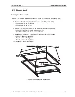
Installing the USB board, DC-IN, FM card and CRT cable
Install the USB board, DC-IN, FM card and CRT cable according to the following
procedures and Figure 4-27.
Note: Be careful of the kill switch button for the USB board. It can be damaged when
installing the USB board. Make sure it is in the correct position.
1.
Connect the FM card cable in to CN2002 and seat the FM card in the correct position.
2.
Seat the DC-IN cable in to the base enclosure.
3.
Seat the CRT cable in the correct position and securing with one M2x4 black flat
head screw.
4.
Seat the RGB cable in the correct position and securing with two M2.8x4.5 black flat
head screws.
Содержание Satellite E100 Series
Страница 13: ...Chapter 1 Hardware Overview i Satellite E100 E105 Maintenance Manual ...
Страница 14: ...1 Hardware Overview ii Satellite E100 E105 Maintenance Manual ...
Страница 23: ...1 1 Features 1 Hardware Overview Figure 1 2 Computer Block Diagram Satellite E100 E105 Maintenance Manual 7 ...
Страница 35: ...2 Troubleshooting 2 i Satellite E100 E105 Maintenance Manual 2 概要 Chapter 2 Troubleshooting ...
Страница 63: ...2 13Cooling Module 2 Troubleshooting Satellite E100 E105 Maintenance Manual 2 25 ...
Страница 64: ...Chapter 3 Diagnostic Programs ...
Страница 67: ......
Страница 106: ...3 5 System Test 3 Diagnostic Programs Satellite E100 Maintenance Manual 39 ...
Страница 125: ...3 Diagnostic Programs 3 8 Video 58 Satellite E100 Maintenance Manual ...
Страница 137: ...Chapter 4 Replacement Procedures 4 1 ...
Страница 138: ...4 Replacement Procedures 4 ii Satellite E100 E105 Satellite ProE100 E105 Maintenance Manual ...
Страница 191: ......
Страница 196: ...6000 1 次 Appendices ...

