


Appendix-4
No.
Photo / Explanatory diagram
Procedure
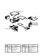
Fuse
Fuse holder
Thermostat
Thermostat
fixing plate
P-shape clamp
Power cord
Cord heater
* Transparent
cover side:
L side
Close-end connector
insulation tape
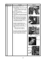
Perform end process and bundling of each cable.
Using fixing screws (Self-tapping screw type-B Ø3.5 ×
8mm), fix the thermostat to the thermostat fixing plate.
Perform end process for various lead cables and connect
them according to the wiring diagram.
Attach #250 Faston and UL-approved sleeves each to
the end of lead cables which are connected to the
thermostat.
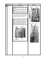
Using insulation tape, apply protective measures to the
connected parts by the close-end connectors.
Using P-shape clamp and the screws (Self-tapping screw
type-B Ø4 × 8mm), fix the power cord to the thermostat
fixing plate.
When the power cord size does not match with P-shape
clamp, procure the most appropriate one at the local site.
Assembly
Return a set of the refrigeration cycle assembly into the outdoor unit base and reassemble sound insulation
board, partition plate assembly, fan motor assembly, and back cabinet as original. Fix the thermostat fixing plate to
the back cabinet, built in the inverter assembly, and then connect various cables. After then, incorporate front
cabinet, upper cabinet, wiring cover, and valve cover as before.
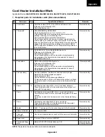
In installation work, connect power cord for the cord heater to another breaker separated from one for power cord
of the air conditioner.
3
4
2-4
5. Drawing of thermostat fixing plate
10
5
56
46
36
8
11
Ø24
26
55˚
42
26
14
11
2-Ø3 burring hole (Downward)
2-Ø3.4 burring hole (Upward)
Ø3.4 burring hole
(Downward)
Material: SGCC-Z08, Thickness: 0.8t
Appendix
Содержание RAV-SP1100AT-E
Страница 118: ......