


103
No.
Part name
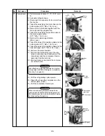
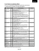
IPDU P.C. board
Procedure
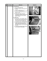
1) Perform works of items
to
.
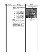
2) Take off screws of the inverter assembly
to separate the inverter assembly.
(M4 × 8, 4 pcs)
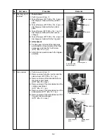
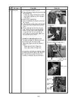
3) Remove the connectors and the lead
wires which are connected from IPDU
P.C. board to the other parts.
1. Connector
CN04: Connection with cycle P.C.
board (3P: White)
CN05: Connection with cycle P.C.
board (2P: White) *(Note 1)
CN06: Connection with cycle P.C.
board (5P: White)
CN13: Connection with cycle P.C.
board (5P: Red) *(Note 1)
CN600: Heat sink sensor (2P: Black)
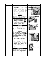
2. Lead wire
CN01: Connection with power
terminal block (Red)
CN02: Connection with power
terminal block (White)
CN03: Connection with inverter box
(Black)
CN09: Connection with compressor
(Red)
CN10: Connection with compressor
(White)
CN11: Connection with compressor
(Black)
Rectifier diode
+
: Red lead wire *Note 2
–
: White lead wire *Note 2
~
: Orange lead wire
(Top)
~
: Brown lead wire
(Bottom)
*(Note 1)
Remove the connectors by releasing lock of
the housing.
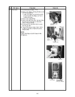
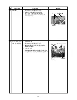
4) Remove the heat sink cover.
(M4 × 8, 2pcs)
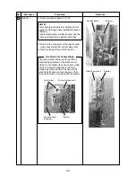
5) Take off two screws which fix the heat
sink and IGBT and also take off support
hooks of the P.C. board (5 positions) to
remove IPDU P.C. board.
6) Mount a new IPDU P.C. board.
*(Note 2)
The rectifier diode has polarity, so be careful
to + and – . If + and – are mistaken, a
trouble is caused.
Remarks
Screw
Screw
Screw
Screw
Heat sink
P.C. board fixing hooks (5 positions)
IPDU P.C. board
Screw
Screw
IPDU P.C. board
Heat sink cover
Содержание RAV-SP1100AT-E
Страница 118: ......