– 103 –
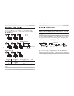
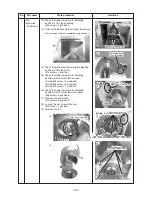
Cord clamp
Cord clamp
Cord clamp
Cord clamp
Fan motor lead wire
Fan motor lead wire
Pull out it toward you
Pull out it toward you
Cord clamp
Cord clamp
Fan motor lead wire
Pull out it toward you
Electric parts box
Screws
Screws
Screws
Screws
Screws
Screws
Screw
Screw
Screw
Connector
Connector
Faston terminal
7)
8)
8)
9)
10)
11)
11)
3)
4)
5)
5)
6)
6)
8)
11)
5)
6)
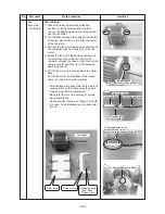
Bundling band
Bundling band
Connector
Bundling band
Fan motor lead wire
No.
1
Part name
Fan
assembly
(Continued)
Work procedure
<Fan/Fan case>
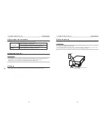
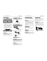
1) Take off screws (2 positions) of the electric
parts box cover.
2) Remove the electric parts box cover.
3) Cut the bundling band (3 positions) which
binds the fan motor lead wires.
4) Remove yellow (F1), blue (F2) and orange (F3)
Faston terminals of the fan motor lead wires.
5) Remove FAN1 (White), FAN2 (Blue) and FAN3
(Red) connectors of the fan motor.
6) Take off screws
(Arrow mark indicating position) of the cabinet.
(M5 screw: 8 positions)
7) Remove the temperature sensor lead wire from
the cord clamp at the rear side of the cabinet.
8) Put the removed electric parts box on the product.
9) Remove lead wires of the fan motor from the
cord clamp in the fan assembly.
10) Take off screws (Arrow mark indicating
position) of the fan assembly.
(M5 screw: 3 positions)
11) Pull out the fan assembly (a fan) toward you.
Remarks


