background image

– 105 –

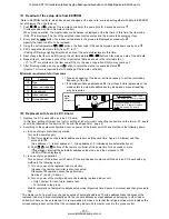
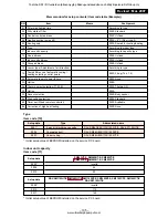
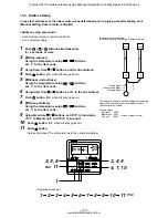
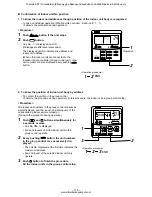
Memorandum for setup contents (Item code table (Example))

Type

Item code [10]

Setup data

0001*

0004

0007

Type

4-way air discharge cassette

Concealed duct

Under ceiling

Abbreviated name

RAV-SM563/803/1103/1403UT-E, RAV-SP1102UT-E

RAV-SM562/802/1102/1402BT-E

RAV-SM562/802/1102/1402CT-E

* Initial setup value of EEPROM installed on the service P.C. board

Indoor unit capacity

Item code [11]

DN

01

02

03

06

0F

10

11

12

13

14

19

1E

28

2A

2b

2E

32

5d

60

8b

Item

Filter sign lighting time

Dirty state of filter

Central control address

Heating suction temp shift

Cooling only

Type

Indoor unit capacity

Line address

Indoor unit address

Group address

Louver type (Adjustment of air direction)

Temp difference of automatic cooling/
heating selecting control points

Automatic reset of power failure

Option

Thermo output selection (T10 ‡B)

Option

Sensor selection

High ceiling selection

Timer set (Wired remote controller)

Correction of high heat feeling

Memo

At shipment

According to type

0000: Standard

0099: Unfixed

0002: +2°C (Floor type: 0)

0000: Shared for cooling/heating

According to model type

According to capacity type

0099: Unfixed

0099: Unfixed

0099: Unfixed

According to type

0003: 3 deg (Ts ± 1.5)

0000: None

0002:

0000: Thermo ON

0000:

0000: Body sensor

0000: Standard

0000: Available

0000: None

Setup data

 0000*

0009

0012

SM563UT-E, SM562BT-E, SM562CT-E
SM803UT-E, SM802BT-E, SM802CT-E

Invalid

56

80

Setup data

 0000*

0015

0017

RAV-SM1103UT-E, SM1403UT-E, SM1102BT-E, SM1402BT-E, SM1102CT-E, SM1402CT-E

RAV-SP1102UT-E

Invalid

110

140

* Initial setup value of EEPROM installed on the service P.C. board

Revised : Mar. 2007

Toshiba SDI / DI tuotteiden jälleenmyyjä pääkaupunkiseudulla on Jäähdytinpalvelu RefGroup Oy

www.ilmalämpöpumput.com

Содержание RAV-SM1102BT-E

Страница 1: ...V SM1102BT E RAV SM1102CT E RAV SM1403UT E RAV SM1402BT E RAV SM1402CT E SUPER DIGITAL INVERTER RAV SP1102UT E OUTDOOR UNIT DIGITAL INVERTER RAV SM563AT E RAV SM803AT E RAV SM1103AT E RAV SM1403AT E SUPER DIGITAL INVERTER RAV SP562AT E RAV SP802AT E RAV SP1102AT E RAV SP1402AT E PRINTED IN JAPAN Mar 2007 ToMo Toshiba SDI DI tuotteiden jälleenmyyjä pääkaupunkiseudulla on Jäähdytinpalvelu RefGroup O...

Страница 2: ...an operation the protective control works to stop the unit operation and the check code P12 may be issued However it is not a trouble When the desired operation has finished be sure to reset the system to clear P12 error code using the leak breaker of the indoor unit Then push the operation stop button of the remote controller to return to the usual operation CONTENTS SAFETY CAUTION 4 1 SPECIFICAT...

Страница 3: ... Board 85 10 4 Troubleshooting Procedure for Each Check Code 86 11 REPLACEMENT OF SERVICE INDOOR P C BOARD 102 12 SETUP AT LOCAL SITE AND OTHERS 106 12 1 Indoor Unit 106 12 2 Setup at Local Site Others 113 12 3 How to set up central control address number 115 13 ADDRESS SETUP 116 13 1 Address Setup 116 13 2 Address Setup Group Control 117 13 3 Address Setup 118 14 DETACHMENTS 120 14 1 Indoor Unit ...

Страница 4: ...anation Indicates prohibited items Forbidden items to do The sentences near an illustrated mark describe the concrete prohibited contents Indicates mandatory items Compulsory items to do The sentences near an illustrated mark describe the concrete mandatory contents Indicates cautions Including danger warning The sentences or illustration near or in an illustrated mark describe the concrete cautio...

Страница 5: ...ed abnormal high pressure generates in the refriger ating cycle and an injury due to breakage may be caused Do not charge refrigerant additionally If charging refrigerant additionally when refrigerant gas leaks the refrigerant composition in the refrigerating cycle changes resulted in change of air conditioner characteristics or refrigerant over the specified standard amount is charged and an abno...

Страница 6: ... and exceeds the limit density an accident of shortage of oxygen is caused For the installation moving reinstallation work follow to the Installation Manual If an incorrect installation is done a trouble of the refrigerating cycle water leak electric shock or fire is caused After repair work has finished check there is no trouble If check is not executed a fire electric shock or injury may be caus...

Страница 7: ...es such as water oxide scales oil etc Use the clean pipes Be sure to brazing with flowing nitrogen gas Never use gas other than nitrogen gas 4 For the earth protection use a vacuum pump for air purge 5 R410A refrigerant is azeotropic mixture type refrigerant Therefore use liquid type to charge the refriger ant If using gas for charging composition of the refrigerant changes and then characteristic...

Страница 8: ... charge Gas leakage check Refrigerant charge R410A air conditioner installation Existence of Whether conven new equipment tional equipment for R410A can be used Yes Note 1 Yes Note 1 Yes No Yes No Yes No Yes Yes Yes No Yes No Note 2 No Conventional air conditioner installation Whether conventional equipment can be used Yes Note 1 No No Yes Yes No Yes No 1 Vacuum pump Use vacuum pump by attaching v...

Страница 9: ...l H M L dB A Sound power level H M L dB A SM563UT E SM803UT E SM1103UT E SM1403UT E SM563AT E SM803AT E SM1103AT E SM1403AT E 5 3 6 7 10 0 12 1 5 6 8 0 11 2 14 0 1 phase 230V 220 240V 50Hz 7 89 7 24 10 11 9 26 14 42 13 21 7 67 16 19 1 65 2 09 3 11 3 77 95 94 98 97 3 21 3 21 3 22 3 21 A A A A 4 5 4 0 4 5 4 0 6 89 6 32 10 69 9 80 14 38 13 18 18 18 16 67 1 44 2 21 3 10 3 88 95 94 98 97 3 89 3 62 3 61...

Страница 10: ...d power level H M L dB A SM563UT E SM803UT E SP1102UT E SM1403UT E SP562AT E SP802AT E SP1102AT E SP1402AT E 5 3 7 1 10 0 12 5 5 6 8 0 11 2 14 0 1 phase 230V 220 240V 50Hz 7 17 6 57 8 95 8 21 11 24 10 31 16 51 15 14 1 53 1 93 2 40 3 56 97 98 97 98 3 46 3 68 4 17 3 51 A A A A 5 62 5 15 9 42 8 63 12 28 11 25 16 60 15 22 1 20 2 03 2 62 3 58 97 98 97 98 4 67 3 94 4 27 3 91 A A A A Zinc hot dipping ste...

Страница 11: ... H M L dB A Sound power level H M L dB A SM562BT E SM802BT E SM1102BT E SM1402BT E SM563AT E SM803AT E SM1103AT E SM1403AT E 5 0 7 1 10 0 12 5 5 6 8 0 11 2 14 0 1 phase 230V 220 240V 50Hz 8 52 7 81 12 23 11 21 16 50 15 10 20 70 19 00 1 78 2 53 3 56 4 42 95 94 98 97 2 81 2 81 2 81 2 83 C C C C 3 0 3 0 3 5 3 0 8 18 7 50 11 65 10 68 14 56 13 35 18 88 17 31 1 71 2 41 3 14 4 03 95 94 98 97 3 27 3 32 3 ...

Страница 12: ... pressure level H M L dB A Sound power level H M L dB A SM562BT E SM802BT E SM1102BT E SM1402BT E SP562AT E SP802AT E SP1102AT E SP1402AT E 5 0 7 1 10 0 12 5 5 6 8 0 11 2 14 0 1 phase 230V 220 240V 50Hz 6 51 5 97 9 74 8 93 11 72 10 74 18 09 16 58 1 39 2 10 2 50 3 90 97 98 97 98 3 60 3 38 4 00 3 21 A A A A 7 26 6 66 9 74 8 93 11 72 10 74 16 70 15 31 1 55 2 10 2 50 3 60 97 98 97 98 3 61 3 81 4 48 3 ...

Страница 13: ...de mm Drain port mm Sound pressure level H M L dB A Sound power level H M L dB A SM562CT E SM802CT E SM1102CT E SM1402CT E SM563AT E SM803AT E SM1103AT E SM1403AT E 5 0 7 0 10 0 12 3 5 6 8 0 11 2 14 0 1 phase 230V 220 240V 50Hz 8 71 7 98 12 23 11 21 16 20 14 90 21 18 19 40 1 82 2 53 3 51 4 52 95 94 98 97 2 75 2 77 2 85 2 72 D D C D 2 5 2 5 3 0 2 5 7 85 7 19 11 94 10 95 14 84 13 61 19 40 17 78 1 64...

Страница 14: ...Liquid side mm Drain port mm Sound pressure level H M L dB A Sound power level H M L dB A SM562CT E SM802CT E SM1102CT E SM1402CT E SP562AT E SP802AT E SP1102AT E SP1402AT E 5 0 7 1 10 0 12 5 5 6 8 0 11 2 14 0 1 phase 230V 220 240V 50Hz 6 61 6 06 9 74 8 93 11 24 10 31 18 09 16 58 1 41 2 10 2 40 3 90 97 98 97 98 3 55 3 38 4 17 3 21 A A A A 7 03 6 44 10 20 9 35 11 72 10 74 17 39 15 94 1 50 2 20 2 50...

Страница 15: ...M1403AT E 10 0 12 5 10 0 12 5 10 0 12 3 11 2 14 0 11 2 14 0 11 2 14 0 Indoor unit 1 phase 230V 220 240V 50Hz 14 40 13 20 19 17 17 57 16 51 15 14 20 71 18 99 16 28 14 92 21 18 19 42 3 11 4 09 3 56 4 42 3 51 4 52 98 97 98 97 98 97 3 22 3 06 2 81 2 83 2 85 2 72 A B C C C D 14 40 13 20 18 74 17 18 14 56 13 35 18 88 17 31 14 84 13 61 19 40 7 78 3 10 4 00 3 14 4 03 3 20 4 14 98 97 98 97 98 97 3 61 3 50 ...

Страница 16: ... 12 5 10 0 12 5 10 0 12 3 11 2 14 0 11 2 14 0 11 2 14 0 Indoor unit 1 phase 230V 220 240V 50Hz 11 24 10 31 16 51 15 14 11 72 10 74 18 09 16 58 11 24 10 31 18 09 16 58 2 40 3 56 2 50 3 90 2 40 3 90 97 98 97 98 97 98 4 17 3 51 4 00 3 21 4 17 3 21 A A A A A A 11 95 10 95 16 60 15 22 11 95 10 95 16 70 15 31 11 95 10 95 17 39 15 94 2 55 3 58 2 55 3 60 2 55 3 75 97 98 97 98 97 98 4 39 3 91 4 39 3 89 4 3...

Страница 17: ...dB A Outside air temperature Cooling C Outside air temperature Heating C SM563AT E SM803AT E SM1103AT E SM1403AT E 1 phase 230V 220 240V 50Hz Power exclusive to outdoor is required Hermetic compressor 1 1 1 6 2 5 3 0 4 4 4 4 1 0 1 7 2 8 2 8 Pulse motor valve 7 5 7 5 7 5 7 5 5 0 5 0 5 0 5 0 30 30 50 50 20g m 40g m 40g m 40g m 21m to 30m 21m to 30m 31m to 50m 31m to 50m 30 30 30 30 30 30 30 30 550 5...

Страница 18: ...A Outside air temperature Cooling C Outside air temperature Heating C SP562AT E SP802AT E SP1102AT E SP1402AT E 1 phase 230V 220 240V 50Hz Power exclusive to outdoor is required Hermetic compressor 2 0 2 0 3 75 3 75 4 4 4 4 1 5 2 1 2 95 2 95 Pulse motor valve 7 5 7 5 7 5 7 5 5 0 5 0 5 0 5 0 50 50 70 70 20g m 40g m 40g m 40g m 21m to 50m 31m to 50m 31m to 70m 31m to 70m 30 30 30 30 30 30 30 30 795 ...

Страница 19: ... C Air flow High Pipe length 7 5m 230V Conditions Indoor DB20 C Outdoor DB7 C WB6 C Air flow High Pipe length 7 5m 230V Conditions Indoor DB27 C WB19 C Outdoor DB35 C Air flow High Pipe length 7 5m 230V Conditions Indoor DB20 C Outdoor DB7 C WB6 C Air flow High Pipe length 7 5m 230V RAV SM1403AT E RAV SM803AT E RAV SM803AT E RAV SM1403AT E RAV SM1403AT E RAV SM1403AT E RAV SM803AT E RAV SM803AT E ...

Страница 20: ...or DB7 C WB6 C Air flow High Pipe length 7 5m 230V RAV SP1102AT E RAV SP1402AT E RAV SP1102AT E RAV SP1402AT E RAV SP802AT E RAV SP562AT E RAV SP802AT E RAV SP1102AT E RAV SP1402AT E RAV SP1102AT E RAV SP1402AT E RAV SP802AT E RAV SP562AT E RAV SP802AT E 0 0 20 40 60 90 80 70 100 2 4 6 8 10 12 14 16 Current A Conditions Indoor DB27 C WB19 C Outdoor DB35 C Air flow High Pipe length 7 5m 230V Condit...

Страница 21: ...33 34 35 36 37 38 39 40 41 42 43 Outdoor temp C Capacity ratio 0 10 20 30 40 50 60 70 80 90 100 110 120 14 12 10 8 6 4 2 0 2 4 6 8 10 Outdoor temp C Capacity ratio Conditions Indoor DB20 C Indoor air flow High Pipe length 7 5m Conditions Indoor DB27 C WB19 C Indoor air flow High Pipe length 7 5m Revised Mar 2007 Toshiba SDI DI tuotteiden jälleenmyyjä pääkaupunkiseudulla on Jäähdytinpalvelu RefGrou...

Страница 22: ...essure H tap Standard L tap High static pressure 1H tap Standard H tap Low static pressure H tap Standard L tap High static pressure 1H tap Standard H tap Low static pressure H tap Standard L tap High static pressure 1H tap Standard H tap Low static pressure H tap Standard L tap High static pressure 1H tap Standard H tap Air volume limit Min Air volume limit Max Air volume limit Min Air volume lim...

Страница 23: ...igh static pressure 2H tap Low static pressure H tap Standard L tap High static pressure 1H tap Standard H tap Low static pressure H tap Standard L tap High static pressure 1H tap Standard H tap Low static pressure H tap Standard L tap High static pressure 1H tap Standard H tap Low static pressure H tap Standard L tap High static pressure 1H tap Standard H tap Air volume limit Max Air volume limit...

Страница 24: ...e under ceiling Standing 850 or less Standing 640 or less Surface under ceiling 840 Hanging bolt Z view Z Drain up standing size Ceiling panel Sold separately Knockout for humidifier 723 Hanging bolt pitch 950 Panel external dimension 840 Unit external dimension 790 Hanging bolt pitch 950 Panel external dimension Electric parts box Refrigerant pipe connecting port A Cable draw in port Refrigerant ...

Страница 25: ...parts box 227 D 88 C 97 35 227 480 840 Unit external dimension C 97 105 105 Ø162 Ø162 130 105 250 270 70 30 173 113 45 105 130 210 Ceiling bottom surface Knockout square hole for divide duct for Ø150 2 positions Knockout square hole for divide duct For Ø150 Drain pipe connecting port SM1103 SM1403 Ø9 5 Ø9 5 A 319 319 D 183 183 C Ø15 9 SP1102 Ø9 5 319 183 Ø15 9 Ø15 9 B 360 Standing 850 or less Stan...

Страница 26: ...41 196 393 498 638 50 131 243 50 Refrigerant pipe connecting port Gas side ØF 174 320 450 Plane view of main unit Check port A 100 300 Pipe side Discharge side NOTE 1 For maintenance of the equipment be sure to install a check port A at the position as shown below NOTE 2 Using the drain up kit sold separately drain up by 300 mm from drain pipe draw out port of the main unit is necessary The drain ...

Страница 27: ...nockout hole Remote controller cable take in port Remote controller cable take in port Knockout hole Outside air take in port Duct sold separately Knockout hole Ø92 Pipe hole on wall Ø100 hole Drain left pipe draw out port Knockout hole Wireless sensor mounting section 562CT 802CT 1102CT 1402CT Model name A B C D 910 1180 1595 855 1125 1540 Ø6 4 Ø12 7 Ø9 5 Ø15 9 Hanging position 84 135 84 262 347 ...

Страница 28: ...h terminal 320 600 483 257 2 Ø11 14 U shape holes For Ø8 Ø10 anchor bolt Suction port Discharge port Discharge port Minimum distance up to wall 2 Ø11 14 long hole For Ø8 Ø10 anchor bolt 500 or more 150 or more 300 or more 150 or more 600 320 320 3 3 54 38 54 38 R15 2 Ø6 hole Product external line Product external line Ø11 14 U shape hole Ø11 14 U shape holes 2 Ø6 hole R15 600 Details of A legs Det...

Страница 29: ...ing port Flare at gas side Ø12 7 RAV SP562AT E Ø15 9 RAV SP802AT E Discharge guide mounting hole 4 Ø4 Embossing 1 1 2 2 795 85 165 60 80 25 60 90 320 28 400 161 58 46 30 45 27 Space required for service 365 600 2 Ø12 17 U shape holes For Ø8 Ø10 Anchor bolt Suction port Discharge port Discharge port Minimum distance up to wall 2 Ø12 17 long hole For Ø8 Ø10 Anchor bolt 500 or more 150 or more 150 or...

Страница 30: ... 17 long hole Discharge guide mounting port 8 Ø3 embossing Mountig bolt hole Ø12 x 17 U shape hole B legs Drain hole Ø20 x 88 Suction port Suction port Drain hole Ø25 Knockout Drain Knockout Drain Discharge port A legs Refrigerant pipe connecting port Ø15 9 flare at gas side 365 600 2 Ø12 x 17 U shape holes For Ø8 Ø10 anchor bolt Suction port Discharge port Discharge port Minimum distance up to wa...

Страница 31: ... 2 step muffler Ø19 05 200L Rotary compressor DA150A1F 20F Heat exchanger Ø8 ripple 2 rows 14 steps FP1 3 flat fin PMV Pulse Motor Valve CAM B30YGTF 2 R410A 1 0 kg Cooling Heating Height difference Section shape of heat insulator Standard Cooling Overload Low load Standard Heating Overload Low load Pressure MPa kg cm G Pd Ps Pd Ps 3 50 0 97 35 7 9 9 3 90 1 08 39 8 11 0 1 90 0 70 19 4 7 1 2 31 0 61...

Страница 32: ...z measured with a clamp meter is 2 times of revolutions rps of the compressor Indoor unit Outdoor unit TCJ sensor Air heat exchanger Strainer TC sensor TD sensor TS sensor TO sensor TE sensor Distributor 4 way valve STF 0213Z 2 step muffler Ø25 200L Rotary compressor DA150A1F 20F Accumulator 1000cc Heat exchanger Ø8 ripple 2 rows 20 steps FP1 3 flat fin PMV Pulse Motor Valve CAM B30YGTF 1 R410A 1 ...

Страница 33: ...e Ø9 5 PMV Pulse Motor Valve UKV 25D22 Height difference Section shape of heat insulator Outer diameter of refrigerant pipe Gas side ØA Liquid side ØB 15 9mm 9 5mm Height difference m Outdoor unit at upper side Outdoor unit at lower side 30 30 Standard Cooling Overload Low load Standard Heating Overload Low load Pressure MPa kg cm G Pd Ps Pd Ps 3 44 0 92 35 1 9 4 3 73 1 18 38 1 12 0 1 49 0 70 15 2...

Страница 34: ...5 9mm 9 5mm Height difference m Outdoor unit at upper side Outdoor unit at lower side 30 30 Standard Cooling Overload Low load Standard Heating Overload Low load Pressure MPa kg cm G Pd Ps Pd Ps 3 52 0 85 35 9 8 7 3 78 1 12 38 6 11 4 1 51 0 71 15 4 7 2 2 88 0 60 29 4 6 1 3 41 1 08 34 8 11 0 2 35 0 24 24 0 2 4 Pipe surface temperature C Discharge TD 87 84 40 85 81 80 Suction TS 8 15 7 1 14 19 Indoo...

Страница 35: ...side ØB 12 7mm 6 4mm Height difference m Outdoor unit at upper side Outdoor unit at lower side 30 15 Height difference Section shape of heat insulator RAV SM563UT E RAV SM562BT E RAV SM562CT E RAV SP562AT E 4 poles are provided to this compressor The compressor frequency Hz measured with a clamp meter is 2 times of revolutions rps of the compressor Standard Cooling Overload Low load Standard Heati...

Страница 36: ...ined For the refrigerating cycles of the other indoor units refer to the corresponding Service Manuals described in the list on the cover Outer diameter of refrigerant pipe Gas side ØA Liquid side ØB 15 9mm 9 5mm Height difference m Outdoor unit at upper side Outdoor unit at lower side 30 15 Height difference Section shape of heat insulator Standard Cooling Overload Low load Standard Heating Overl...

Страница 37: ... differs according to the models to be combined For the refrigerating cycles of the other indoor units refer to the corresponding Service Manuals described in the list on the cover Outer diameter of refrigerant pipe Gas side ØA Liquid side ØB 15 9mm 9 5mm Height difference m Outdoor unit at upper side Outdoor unit at lower side 30 15 Height difference Section shape of heat insulator Standard Cooli...

Страница 38: ... according to the models to be combined For the refrigerating cycles of the other indoor units refer to the corresponding Service Manuals described in the list on the cover Outer diameter of refrigerant pipe Gas side ØA Liquid side ØB 15 9mm 9 5mm Height difference m Outdoor unit at upper side Outdoor unit at lower side 30 15 Height difference Section shape of heat insulator Standard Cooling Overl...

Страница 39: ... Motor drive circuit Power supply circuit DC20V DC15V DC12V DC7V Fuse F302 T3 15A 250V 1 2 1 2 3 3 1 2 1 2 3 3 1 2 3 4 4 5 5 DP CN333 WHI CN334 WHI CN68 BLU CN304 GRY 1 2 CN66 WHI CN41 BLU CN309 YEL CN60 WHI 1 2 CN32 WHI 1 2 3 4 5 6 1 2 3 4 5 CN50 WHI 1 2 3 4 5 1 2 3 4 5 CN51 RED CN40 BLU Terminal for central remote controller Connection interface option P C Board 1 2 3 4 5 1 2 3 4 5 6 CN61 YEL CN...

Страница 40: ...e F302 T3 15A 250V 1 2 1 2 3 3 1 2 1 2 3 3 1 2 3 4 4 5 5 DP CN333 WHI CN334 WHI CN68 BLU CN304 GRY 1 2 CN66 WHI Reactor Capacitor CN41 BLU CN309 YEL CN60 WHI 1 2 CN32 WHI 1 2 3 4 5 6 1 2 3 4 5 6 CN61 YEL CN67 BLK RED WHI BLK BLK BLK BLK P301 1 1 2 2 3 1 2 3 3 B A FAN DRIVE MCC 1402 Control P C Board for Indoor Unit Indoor unit earth screw RY 302 Fuse F301 250V T6 3A RY 303 WHI 3 2 1 3 2 1 N L Sing...

Страница 41: ...A 250V 1 2 1 2 3 3 1 2 1 2 3 3 1 2 3 4 4 5 5 DP CN333 WHI CN334 WHI CN68 BLU CN304 GRY 1 2 CN66 WHI Reactor Capacitor CN41 BLU CN309 YEL CN60 WHI 1 2 CN32 WHI 1 2 3 4 5 6 1 2 3 4 5 6 CN61 YEL CN67 BLK RED WHI BLK BLK BLK BLK P301 1 1 2 2 3 1 2 3 3 B A FAN DRIVE MCC 1402 Control P C Board for Indoor Unit Indoor unit earth screw RY 302 Fuse F301 250V T6 3A RY 303 WHI 3 2 1 3 2 1 N L Single phase 220...

Страница 42: ... 4 5 2 3 1 2 2 3 3 1 1 2 2 3 3 1 1 1 1 2 2 3 3 1 1 TE Condenser pipe temp sensor For optional P C Board Reactor Reactor Coil for 4 WAY VALVE F01 Fuse T25A AC250V F03 Fuse T3 15A AC250V Fuse 250V T6 3A To indoor Power supply 220 240V 50Hz RED BLK P30 P31 CN605 BLK P11 RED Compressor WHI BLK P04 P05 P06 P19 P34 DB01 DB02 C12 C14 L03 C13 P35 P20 P21 P22 P23 P24 P25 ORN YEL YEL BRN YEL P18 P08 SW802 M...

Страница 43: ...LE P17 P18 P19 P28 GRY P29 ORN P21 BRN P24 RED P20 CM Compressor RY01 GRY GRY P13 P12 2 2 1 1 WHI WHI RED WHI BLK P09 P08 Reactor Reactor RED GRY PNK YEL Fuse T6 3A 250V To indoor unit Power supply 220 240V 50Hz N L 1 2 3 1 3 3 1 1 3 3 1 5 5 4 4 5 5 6 6 2 2 3 3 1 1 4 4 5 5 2 2 3 3 1 1 4 4 5 5 2 2 3 3 1 1 4 4 5 5 2 2 3 3 1 1 PMV 2 2 3 3 1 1 FM RED RED Coil for 4 WAY Valve WHI BLK RED WHI BLK CN02 B...

Страница 44: ...301 WHI CN300 WHI IGBT MODULE P17 P18 P19 P28 GRY P29 ORN P21 BRN P24 RED P20 CM Compressor RY01 GRY GRY P13 P12 2 2 1 1 WHI WHI RED WHI BLK P09 P08 Reactor Reactor Fuse F300 T5A 250V RED RED GRY PNK YEL Fuse T6 3A 250V To indoor unit Power supply 220 240V 50Hz N L 1 2 3 1 3 3 1 1 3 3 1 5 5 4 4 5 5 6 6 2 2 3 3 1 1 4 4 5 5 2 2 3 3 1 1 PMV 2 2 3 3 1 1 FM Coil for 4 WAY Valve GRN YEL WHI RED RED WHI ...

Страница 45: ...P21 BRN P24 RED P20 CM Compressor RY01 GRY GRY P13 P12 2 2 1 1 WHI WHI RED WHI BLK P09 P08 Reactor Reactor Fuse F300 T5A 250V RED RED GRY PNK YEL Fuse T6 3A 250V To indoor unit Power supply 220 240V 50Hz N L 1 2 3 1 3 3 1 1 3 3 1 5 5 4 4 5 5 6 6 2 2 3 3 1 1 4 4 5 5 2 2 3 3 1 1 PMV 2 2 3 3 1 1 FM Coil for 4 WAY Valve GRN YEL WHI RED RED WHI WHI BLK WHI RED RED WHI BLK CN02 BLK Serial commu nication...

Страница 46: ...5 mm Ø6 mm 1200 mm Ø6 mm 1200 mm FS 0218 102 ADP 1409 Specifications Output Rated 60 W 220 240 V 10 kΩ at 25 C 10 kΩ at 25 C 10 kΩ at 25 C No 1 2 3 4 5 6 Parts name Fan motor Thermo sensor TA sensor Heat exchanger sensor TCJ sensor Heat exchanger sensor TC sensor Float switch Drain pump motor Type SWF 200 90 1R 155 mm Ø6 mm 1200 mm Ø6 mm 1200 mm FS 0218 102 ADP 1409 Specifications Output Rated 90 ...

Страница 47: ...ut Rated 120 W 220 240 V Output Rated 120 W 220 240 V 10 kΩ at 25 C 10 kΩ at 25 C 10 kΩ at 25 C 10 mH 1 A No 1 2 3 4 5 6 7 8 Parts name Fan motor SM562CT E Fan motor SM802CT E Fan motor SM1102CT E SM1402CT E Thermo sensor TA sensor Heat exchanger sensor TCJ sensor Heat exchanger sensor TC sensor Louver motor Reactor Type SWF 280 60 1R SWF 280 60 2R SWF 280 120 2R 155 mm Ø6 mm 1200 mm Ø6 mm 1200 mm...

Страница 48: ...otect 4 way valve solenoid coil Compressor thermo Protection Coil Pulse Motor Valve Type ICF 140 43 4R DA150A1F 20F CH 57 STF 01AJ502E1 US 622 CAM MD12TF 6 Specifications Output Rated 43 W 3 phase 4P 1100 W 10 mH 16 A 10 kΩ at 25 C 10 kΩ at 25 C 10 kΩ at 25 C 50 kΩ at 25 C T3 15 A AC 250 V 25 A AC 250 V AC 220 240 V OFF 125 4 C ON 90 5 C 6 2 Outdoor Unit RAV SM563AT E No 1 2 3 4 5 6 7 8 9 10 11 12...

Страница 49: ...ect 4 way valve solenoid coil Compressor thermo Protection Coil Pulse Motor Valve Type ICF 140 63 2R DA420A3F 21M CH 62 VHV 01AJ502E1 US 622 UKV U011E Specifications Output Rated 63 W 3 phase 4P 3500 W 6 mH 18 5 A 10 kΩ at 25 C 10 kΩ at 25 C 10 kΩ at 25 C 50 kΩ at 25 C T3 15 A AC 250 V 25 A AC 250 V AC 220 V OFF 125 4 C ON 90 5 C RAV SP562AT E RAV SP802AT E No 1 2 3 4 5 6 7 8 9 10 11 12 13 Parts n...

Страница 50: ...SM563UT E RAV SM803UT E RAV SM1103UT E RAV SM1403UT E RAV SP1102UT E No 1 2 Parts name Float switch Drain pump motor Type FS 0218 102 ADP 1415 Specifications No 1 2 Parts name Motor louver Type MP24ZN Specifications DC 12 V Revised Mar 2007 Toshiba SDI DI tuotteiden jälleenmyyjä pääkaupunkiseudulla on Jäähdytinpalvelu RefGroup Oy www ilmalämpöpumput com ...

Страница 51: ...l injury may be caused 5 After completion of installation work check to make sure that there is no refrigeration gas leakage If the refrigerant gas leaks into the room coming into contact with fire in the fan driven heater space heater etc a poisonous gas may occur 6 When an air conditioning system charged with a large volume of refrigerant is installed in a small room it is necessary to exercise ...

Страница 52: ...pipe interior that no other oil other than lubricating oils used in the installed air conditioner is used and that refrigerant does not leak When using lubricating oils in the piping processing use such lubricating oils whose water content has been removed When stored be sure to seal the container with an airtight cap or any other cover 1 Flare Processing Procedures and Precautions a Cutting the P...

Страница 53: ...2 7 15 9 Thickness mm 0 8 0 8 0 8 1 0 A mm Flare tool for R410A clutch type 0 to 0 5 0 to 0 5 0 to 0 5 0 to 0 5 Conventional flare tool Clutch type Wing nut type 1 0 to 1 5 1 5 to 2 0 1 0 to 1 5 1 5 to 2 0 1 0 to 1 5 2 0 to 2 5 1 0 to 1 5 2 0 to 2 5 Nominal diameter 1 4 3 8 1 2 5 8 Outer diameter mm 6 4 9 5 12 7 15 9 Thickness mm 0 8 0 8 0 8 1 0 A mm Flare tool for R22 clutch type 0 to 0 5 0 to 0 ...

Страница 54: ...ence values NOTE When applying oil to the flare surface be sure to use oil designated by the manufacturer If any other oil is used the lubricating oils may deteriorate and cause the compressor to burn out Table 7 2 7 Tightening torque of flare for R410A Reference values Nominal diameter 1 4 3 8 1 2 5 8 3 4 Outer diameter mm 6 4 9 5 12 7 15 9 19 0 Thickness mm 0 8 0 8 0 8 1 0 1 0 Dimension mm A B C...

Страница 55: ... indicated 0 1 Mpa 76 cmHg place the handle Low in the fully closed position and turn off the vacuum pump s power switch Keep the status as it is for 1 to 2 minutes and ensure that the compound gauge s pointer does not return Set the refrigerant cylinder to the electronic balance connect the connecting hose to the cylinder and the connecting port of the electronic balance and charge liquid refrige...

Страница 56: ...n iron copper or copper alloy and is relatively expensive though it excels in solderability 2 Phosphor bronze brazing filler Phosphor bronze brazing filler is generally used to join copper or copper alloy 3 Low temperature brazing filler Low temperature brazing filler is generally called solder and is an alloy of tin and lead Since it is weak in adhesive strength do not use it for refrigerant pipe...

Страница 57: ...dding water to the flux use water which does not contain chlorine e g distilled water or ion exchange water 4 Remove the flux after brazing 7 5 3 Brazing As brazing work requires sophisticated techniques experiences based upon a theoretical knowledge it must be performed by a person qualified In order to prevent the oxide film from occurring in the pipe interior during brazing it is effective to p...

Страница 58: ... the cause of trouble will occur 8 Installation and removal of the air conditioner are repeated with temporary installation by lease and etc 9 In case that type of the refrigerator oil of the existing air conditioner is other than the following oil Mineral oil Suniso Freol S MS Synthetic oil alkyl benzene HAB Barrel freeze ester series PVE only of ether series Winding insulation of the compressor ...

Страница 59: ...nIn case that the gas pipe Ø19 mm is used for the outdoor unit of SM803 3 HP or higher Gas pipe size of our R410A model 3 to 5 HP is Ø15 9 mm Turn the existing pipe switch on the cycle control P C board of the outdoor unit to ON side At shipment from factory OFF ON for existing pipe Refer to the table below Be sure to set the contents in the table below in order to restrict the refrigerating cycle...

Страница 60: ...ock because the control P C board is electrified 7 6 7 Recovery method of refrigerant for RAV SM1103AT E SM1403AT E When recovering refrigerant in case of reinstalla tion of the indoor or outdoor unit etc use the refrigerant recovery switch SW802 on the cycle control P C board of the outdoor unit Work procedure 1 Turn on the power supply 2 Using the remote controller set FAN operation to the indoo...

Страница 61: ...mer Secondary battery DC5V 2 CN2 CN1 A B 1 2 3 Outdoor unit Same as the left 1 2 A B 1 2 3 Outdoor unit Same as the left 1 1 Connection Interface is attached to master unit In case of group control operation 2 Weekly timer is not connectable to the sub remote controller P C board MCC 1440 Central control remote controller Option CPU EEPROM Power circuit Power circuit Power circuit Function setup S...

Страница 62: ... HEAT operation mode is automatically selected by Ta and Ts for operation 1 Judge the selection of COOL HEAT mode as shown in the figure above When 10 minutes passed after thermostat had been turned off the heating operation Thermo OFF is exchanged to cooling operation if Tsh exceeds 1 5 or more COOL OFF and COOL ON in the figure indicate an example When 10 minutes passed after thermostat had been...

Страница 63: ...ucted to the outdoor unit 1 Operation with HH H L or AUTO mode is performed by the command from the remote control ler 2 When the air speed mode AUTO is selected the air speed varies by the difference between Ta and Ts COOL Controlling operation in case when thermo of remote controller works is same as a case when thermo of the body works If the air speed has been changed once it is not changed fo...

Страница 64: ...tes one in automatic heating operation In Tc 60 C the air speed increases by 1 step In heating operation the mode changes to LL if thermo stat is turned off If Ta 25 C when heating operation has started and when defrost operation has been cleared it operates with HIGH H mode or HH for 1 minute from when Tc has entered in E zone of cool air discharge preventive control Item 6 In automatic cooling h...

Страница 65: ...ng operation the freeze preventive control works if 4 way valve is not exchanged and the condi tion is satisfied However the temperature for J zone dashing control is changed from 2 C to 5 C 1 The heating operation is performed as follows based on the detected temperature of Tc sensor or Tcj sensor When M zone is detected the commanded fre quency is decreased from the real operation fre quency Aft...

Страница 66: ...position moves necessarily to downward dis charge position once to return to the set posi tion The louver position can be set up in the follow ing operation range In cooling dry operation In heating fan operation In group twin triple operation the louver posi tions can be set up collectively or individually 2 Swing setup The swinging position can be moved in the following operation range All modes...

Страница 67: ...tch S003 from OFF to ON Attach the sensor P C board cover and mount the adjuster with sensors to the ceiling panel Turn on the power of the set 3 Push ON OFF button of the wireless remote control ler and set the operation mode to COOL or HEAT using MODE button During test run operation all the display lamps of wireless remote controller sensors flash Do not use other mode than COOL HEAT mode An er...

Страница 68: ...culate correction value of the setup temperature 4 The setup temperature is shifted every 20 minutes and the shifted range is as follows In cooling time 1 5 to 1 0K In heating time 1 5 to 1 0K The louver angle is displayed setting 0 as Full close 1 In the initial operation after power ON the position is automatically controlled according to the operating status COOL HEAT 2 After then a louver posi...

Страница 69: ...ding to the following figure if To 15 C It cannot be operated on the remote controller at indoor unit side Stop status is held 1 When the fan operation has started positioning of the stator and the rotor are performed Moves slightly with tap sound 2 The motor operates according to the command from the indoor controller NOTES When the fan rotates while the air conditioner stops due to entering of o...

Страница 70: ...an output Optional output TC sensor HA T10 CHK DISP TA sensor Remote controller inter unit cable EXCT Used for servicing TCJ sensor 1 Drain pump output Remote controller power supply LED Optional power supply Indoor Outdoor inter unit cable Filter Option error input EEPROM Connection interface Microcomputer operation LED Toshiba SDI DI tuotteiden jälleenmyyjä pääkaupunkiseudulla on Jäähdytinpalvel...

Страница 71: ... is in heating system HEAT HEAT in AUTO cooling heating ON during indoor fan ON Air purifier is used Interlock cable When continued for 1 minute Check code L30 is output and forced operation stops Option error input is controlled Protective operation for device attached to outside is displayed Setting of option error input is performed from remote controller DN 2A Used for operation check of indoo...

Страница 72: ...wer supply lead Black N phase power supply lead White Serial lead Orange Reactor lead connector White CN300 Fan motor connector CN602 Outdoor temperature TO sensor connector CN806 Optional connector CN600 Heat exchange temperature TE sensor connector CN603 Suction temperature TS sensor connector CN601 Discharge temperature TD sensor connector CN701 4 way valve connector RY701 4 way valve relay IC8...

Страница 73: ...ector CN804 TE sensor CN604 TO sensor CN601 TD sensor CN600 Fan motor output CN301 Fan motor revolution CN300 DC15V input To MCC 1438 CN04 DC320V input To MCC 1438 CN03 Serial signal To terminal block CN02 AC input To MCC 1438 CN01 4 way valve CN700 RAV SM1103AT E RAV SM1403AT E RAV SP562AT E RAV SP802AT E MCC 1531 Revised Mar 2007 Toshiba SDI DI tuotteiden jälleenmyyjä pääkaupunkiseudulla on Jääh...

Страница 74: ...sor CN604 TO sensor CN601 TD sensor CN600 Fan motor 1 Upper output CN301 Fan motor 1 Upper revolution CN300 DC15V input To MCC 1438 CN04 DC320V input To MCC 1438 CN03 Serial signal To terminal block CN02 AC input To MCC 1438 CN01 4 way valve CN700 Fan motor 2 Lower revolution CN302 Fan motor 2 Lower output CN303 RAV SP1102AT E RAV SP1402AT E MCC 1531 Toshiba SDI DI tuotteiden jälleenmyyjä pääkaupu...

Страница 75: ...8 Black P21 Orange P24 Brown Reactor Connector Capacitor Mains Neutral input CN02 Mains Live input CN01 DC320V output To MCC 1531 CN04 Earth ground CN03 TH sensor CN600 Rectifier RAV SM1103AT E RAV SM1403AT E RAV SP562AT E RAV SP802AT E RAV SP1102AT E RAV SP1402AT E IPDU MCC 1438 Revised Mar 2007 Toshiba SDI DI tuotteiden jälleenmyyjä pääkaupunkiseudulla on Jäähdytinpalvelu RefGroup Oy www ilmaläm...

Страница 76: ...emperature has not lower or the discharge temperature has rapidly risen during PMV control It subdivides the frequency control up to a unit of 0 6 Hz to stabilize the cycle 2 When the discharge temperature is detected in an abnormal stop zone the unit stops the compres sor and restarts after 2 minutes 30 seconds The error counter is cleared when it has continued the operation for 10 minutes If the...

Страница 77: ...onds to the zone in the following table After then the fan is controlled by TE sensor temperature S Considering a case that TE sensor has come out of the holder the fan is controlled so that revolution frequency of the fan increases regardless of TE if temperature of TD sensor has risen The operation frequency differs according to the model type SM56 SM80 SM110 SM110 a b 36 32 29 26 Temp range 29 ...

Страница 78: ...allation otherwise a trouble of the compressor may be caused As same as a test run it is recommended to turn on power of the compressor beforehand when starting operation after power of the compressor has been interrupted for a long time 3 A judgment for electricity is performed by TD and TO sensors If TO sensor is defective a backup control is automatically performed by TE sensor For a case of de...

Страница 79: ...The minimum TE value between 10 and 15 minutes after heating operation has started is stored in memory as TE0 0 10 15 c b a d min TE ºC 4 5 6 10 10 13 25 18 Numerals enclosed with parentheses represent numeral values of SM110 and SM140 A z A zone one B z B zone one C z C zone one D z D zone one A zone B zone C zone D zone A zone B zone C zone D zone Defrost operation is performed in this zone when...

Страница 80: ...cooling operation Is not defrost operation performed 4 ON OFF operation cannot be performed from remote controller Is not the control operation performed from outside remote side Is not automatic address being set up When the power is turned on at the first time or when indoor unit address setting is changed the operation cannot be performed for maximum approx 5 minutes after power ON b Did you re...

Страница 81: ...eration performed from outside remote side Is not automatic address being set up a Did you return the cabling to the initial positions b Are connecting cables between indoor unit and receiving unit correct 2 Troubleshooting procedure When the power is turned on at the first time or when indoor unit address setting is changed the operation cannot be performed for maximum approx 5 minutes after powe...

Страница 82: ...rror is detected Displayed when error is detected Displayed when error is detected Displayed when error is detected Displayed when error is detected Displayed when error is detected Displayed when error is detected Displayed when error is detected Judgment and measures 1 Check cables of remote controller and communication adapters Handy remote controller LCD display OFF Disconnection Central remot...

Страница 83: ... error is detected Displayed when error is detected Displayed when error is detected Displayed when error is detected Displayed when error is detected Displayed when error is detected Displayed when error is detected Displayed when error is detected Displayed when error is detected Displayed when error is detected Displayed when error is detected Displayed when error is detected Judgment and measu...

Страница 84: ...controller side Signal sending error to indoor unit Detected at remote controller side Multiple master remote controllers are recognized Detected at remote controller side Duplicated indoor central addresses on communication of central control system Detected by central controller side Status of air conditioner Stop Stop Automatic restart When there is center operation continues Stop Automatic res...

Страница 85: ...n Check code Type A Type B F06 18 F04 19 F06 18 F08 1B P03 1E P22 1A L29 1C P04 21 P26 14 P29 16 H03 17 H02 1D H01 1F LED display D800 D801 D802 D803 Red Yellow Yellow Yellow l l l l l l l l l l l l l l l l l l l l l l l l l l l l l l l l l l 10 3 Error Mode Detected by LED on Outdoor P C Board RAV SM1103AT E RAV SM1403AT E RAV SP562AT E RAV SP802AT E RAV SP1102AT E RAV SP1402AT E SW801 LED displa...

Страница 86: ...tion of connector Check circuit cables Check power connection of indoor unit Turn on power again Check indoor P C board MCC 1402 Defect Replace Correct as a master unit a sub unit Remote controller address connector Check remote controller P C board Defect Replace Correct as a master unit a sub unit Remote controller address connector Check remote controller P C board Defect Replace NO YES NO NO N...

Страница 87: ...s correct Does case thermo operate Are 1 2 3 inter unit cables normal Are connections from connectors of inter terminal blocks 1 2 3 of indoor outdoor units normal Does voltage between 2 and 3 of inter terminal blocks 1 2 3 of indoor unit vary Check indoor P C board MCC 1402 Defect Replace As shown in the following figure perform measurement within 20 seconds after power ON Black White 3 2 1 Inter...

Страница 88: ...e Check indoor control P C board MCC 1402 Defect Replace NO NO YES YES YES NO NO Is capacity of indoor unit unset YES NO E10 error E18 error E08 L03 L07 L08 error E08 Duplicated indoor unit numbers L03 Two or more master units in a group control L07 One or more group addresses of Individual in a group control L08 Unset indoor group address 99 If the above is detected when power has been turned on ...

Страница 89: ... of connector Replace TA sensor Refer to Characteristics 1 Correct connection of connector Check drain pipe etc Check and correct cabling wiring Check indoor P C board MCC 1402 Defect Replace Check indoor P C board MCC 1402 Defect Replace Check indoor P C board MCC 1402 Defect Replace Replace drain pump Check cabling NO NO NO NO NO YES YES YES YES YES Is connection of float switch connector Indoor...

Страница 90: ...e pin voltage swings between 0 to 5V voltage Between and 5V Check indoor P C board MCC 1402 Defect Replace Remove connectors CN333 and CN334 of indoor unit P C board MCC 1402 Replace indoor fan motor Replace indoor fan motor Replace indoor fan motor YES NO NO NO NO NO YES YES YES YES Turn off the power Is resistance value of fan motor connector CN333 at motor side of indoor P C board MCC 1402 corr...

Страница 91: ...lues between Yellow lead and Pink lead of motor position detection of connector CN300 is normal Normal fan motor Control or CDB P C board Defective fan motor NOTE However GND circuit error inside of the motor is rarely detected even if the above check is carried out When the circuit does not become normal even if P C board has been replaced replace outdoor fan motor 1 2 2 3 3 1 1 4 Control P C boa...

Страница 92: ...l Are characteristics of TC sensor resistance value normal Check and correct circuit Correct connection of connector Replace TC sensor NO NO NO YES YES YES NO NO YES NO YES YES Check indoor P C board MCC 1402 Defect Replace Is connection of TC sensor connector Indoor P C board CN101 normal Are characteristics of TC sensor resistance value normal P19 error In cooling operation if high pressure is a...

Страница 93: ...control P C board of RAV SM563AT E SM803AT E Is power voltage normal Is not AC fuse fused Check and correct circuit cables Correct connection of connector Check and correct reactor connection Are connections of cabling connector normal Does RY01 relay of IPDU operate Are not P26 and 14 errors output when an operation is performed by removing 3P connector of compressor Replace IPDU Replace control ...

Страница 94: ...t winding opened Compressor error Replace Compressor error Replace Compressor error Replace Check and correct circuit cables Check and correct circuit cabling such as cabling to compressor Check IPDU P C board Defect Replace Check IPDU Defect Replace For RAV SM563AT E SM803AT E replace control P C board YES YES NO NO NO YES P29 error H03 error Revised Mar 2007 Toshiba SDI DI tuotteiden jälleenmyyj...

Страница 95: ...sensor YES NO Is connection of TO sensor connector of CDB CN601 normal Correct connection of connector Check CDB Defect Replace Refer to Characteristics 5 For RAV SM563AT E SM803AT E CN602 TO sensor YES NO Are characteristics of TO sensor resistance value normal Replace TO sensor YES For RAV SM563AT E SM803AT E CN600 TE sensor and CN603 TS sensor For RAV SM563AT E SM803AT E CN601 TD sensor Are con...

Страница 96: ...IPDU P C board error Defect Replace IPDU P C board error Defect Replace Check TE and TS sensors Replace Check electron expansion valve Replace Is there no slackened refrigerant Does electron expansion valve normally operate Is power voltage normal Is compressor normal Are connections of cable connector normal Check and correct circuit cabling such as cabling to compressor phase missing and connect...

Страница 97: ...rect the cabling and connection of connector Improve and delete the cause Replace TD sensor Improve power line Improve and delete the cause Check and correct circuit cables Check CDB Defect Replace Check and correct the charged refrigerant amount For RAV SM563AT E SM803AT E replace control P C board Check IPDU Defect Replace For RAV SM563AT E SM803AT E replace control P C board NO NO NO NO NO NO N...

Страница 98: ...r Check TE TC TS sensors Replace electron expansion valve Replace TD TO and TC sensors Check CDB Defect Replace Does cooling outdoor fan normally operate Does PMV normally operate Is fan motor normal Replace fan motor Correct coming off Are characteristics of TD TO TC sensor resistance values normal Check charged refrigerant amount Check liquid gas valves Check abnormal overload NO NO NO NO NO NO ...

Страница 99: ...P C board and connectors CN51 of indoor P C board normal Check connections of A B terminal blocks Correct communication line of remote controller Check central controller Defect Replace Check indoor P C board MCC 1402 Defect Replace Check connection interface P C board Defect Replace Can handy remote controller control normally other indoor units Can central remote controller control normally othe...

Страница 100: ...ioner stops F29 error 12 error F29 error or 12 error indicates detection of trouble which occurred on IC10 non volatile memory EEPROM on the indoor unit P C board during operation of the air conditioner Replace the service P C board If EEPROM has not been inserted when the power was turned on or if EEPROM data never be read written the automatic address mode is repeated In this time the central co...

Страница 101: ...kW 10 C or higher Caracteristics 4 Temperature C TC TCJ sensor TE TO TS sensor TD sensor TA sensor 20 10 0 10 20 40 30 50 200 100 20 10 0 0 10 0 10 20 40 30 50 60 70 40 30 20 10 0 0 10 10 30 20 40 50 60 70 200 100 20 10 0 0 50 100 10 4 2 Relational Graph of Temperature Sensor Resistance Value and Temperature Toshiba SDI DI tuotteiden jälleenmyyjä pääkaupunkiseudulla on Jäähdytinpalvelu RefGroup Oy...

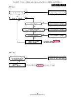
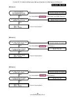
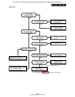
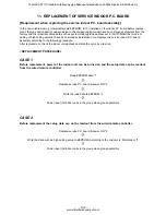
Страница 102: ...lacement check the indoor unit address and also the cycle by a test run REPLACEMENT PROCEDURE CASE 1 Before replacement power of the indoor unit can be turned on and the setup data can be readout from the wired remote controller Read EEPROM data 1 ò Replace service P C board power ON 2 ò Write the read data to EEPROM 3 ò Power reset All indoor units in the group when group operation CASE 2 Before ...

Страница 103: ...cement the mode enters in automatic address setup mode and a manual resetting may be required r2 Replacement of service P C board 1 Replace the P C board with a service P C board In this time setting of jumper line cut or setting of short circuit connecting connectors on the former P C board should be reflected on the service P C board See Appendix 1 page 4 2 According to the system configuration ...

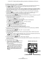
Страница 104: ...o the attached table 6 Push SET button OK when the display goes on 7 Push TEST button to return the status to usual stop status 6 Approx 1 minute is required to start handling of the remote controller 5 Next write the contents which have been set up at the local site such as the address setup in EEPROM Repeat the above procedure 1 and 2 6 Using the set temperature buttons set 01 to the item code D...

Страница 105: ...ts Automatic reset of power failure Option Thermo output selection T10 B Option Sensor selection High ceiling selection Timer set Wired remote controller Correction of high heat feeling Memo At shipment According to type 0000 Standard 0099 Unfixed 0002 2 C Floor type 0 0000 Shared for cooling heating According to model type According to capacity type 0099 Unfixed 0099 Unfixed 0099 Unfixed Accordin...

Страница 106: ...utes timer release function is provided to this remote controller Wireless remote controller 4 way Air Discharge Cassette Type only 1 Turn off power of the unit Remove the adjuster attached with sensors from the ceiling panel For removing refer to the Installation manual attached to the ceiling panel Be careful to handle the adjuster because cables are connected to the sensor Remove the sensor cov...

Страница 107: ...s Small screw Spacer Notch Nameplate Under Ceiling Type only 1 Turn off power of the air conditioner Remove the adjust corner cap attached with sensor section from the ceiling panel For removing method follow to the installation manual attached to the ceiling panel Be careful to handle the sensor section because cables are connected to the sensor section Remove the sensor cover from the adjust cor...

Страница 108: ...o 19 C push Temperature set button to set to 29 C After checking the receiving sound Pi immediately After checking the receiving sound Pi immediately push Temperature set button to set to 18 C push Temperature set button to set to 30 C Then repeat the procedure 4 5 4 5 After approx 10 seconds all the display lamps on the sensor part of wireless remote controller Operation Green Timer Green and Rea...

Страница 109: ... type 0000 Unfixed 0009 56 type 0012 80 type 0015 110 type 0017 140 type 0001 No 1 unit to 0030 No 30 unit 0001 No 1 unit to 0064 No 64 unit 0000 Individual 0001 Master of group 0002 Sub of group 0000 0 deg to 0010 10 deg For setup temperature reversal of COOL HEAT by Data value 2 0000 None 0001 Restart 0000 Indoor thermo ON 0001 Output of outdoor comp ON receiving 0000 Body TA sensor 0001 Remote ...

Страница 110: ... Sub Remote controller switch Master Sold separately 2 1 3 2 1 3 B A B A B A Sold separately 1 2 1 2 1 2 Remote controller Inside of the rear side Sub remote controller Master remote controller DIP switch Sensor cover Adjust corner cap 1 2 3 4 ON Sensor P C board S003 Bit 1 OFF to ON ON 1 2 3 4 2 3 4 Wireless remote controller Under Ceiling Type only How to set wireless remote controller to sub re...

Страница 111: ...emperature of indoor units and outdoor unit in a group control can be monitored by pushing UNIT button to select the indoor unit to be monitored 4 Pushing TEST button returns the display to usual display 1 Only master unit in group control 1 2 3 4 Operation procedure Returned to usual display 1 4 2 3 ON OFF FAN TEMP SWING FIX TIME MODE VENT UNIT SET CL FILTER RESET TEST TIMER SET UNIT No DATA SET ...

Страница 112: ...etting on the remote controller System example 1 Display range on remote controller The setup range Operation mode Air volume select Setup temp of the indoor unit which was set to the master unit is reflected on the remote controller 2 Address setup Turn on power of the indoor unit to be controlled in a group within 3 minutes after setting of automatic address If power of the indoor unit is not tu...

Страница 113: ...MCC 1440 Indoor unit TCC LINK Communication units Total 64 units Communication distance 2000 m CN050 CN041 Terminal block A B Central controller Indoor units in all refrigerant lines Max 64 units If mixed with multi model Link wiring multi indoor units are included However group sub units and twin triple sub units of customized setup are not included in number of the units Central control device U...

Страница 114: ...30V serial Central control system wiring Master unit Master unit Sub unit Sub unit Sub unit Wiring for No 1 and 2 only Remote controller Remote controller Remote controller Remote controller Remote controller wiring Group operation Max 8 units Twin Triple operation Example of triple OFF at shipment from factory OFF at shipment from factory Line address SW01 Bit 1 SW01 Bit 2 Remarks 1 ON OFF Turn S...

Страница 115: ...ed first the unit No RLL is displayed and all the indoor units in the group control are selected In this time fans of all the selected indoor units are turned on Fig 1 Keep RLL displayed status without pushing UNIT button In case of individual remote controller which is not group controlled Line address and Indoor unit address are displayed 2 Using temperature setup TEMP buttons specify item code ...

Страница 116: ... is connected to each indoor unit respectively in the group operation even if multiple refrigerant lines are provided the automatic address setup completes with power ON of the outdoor unit The operation of the remote controller is not accepted while automatic address works Approx 4 to 5 minutes When the following addresses are not stored in the neutral memory IC10 on the indoor P C board a test r...

Страница 117: ...ich communicates serially with the outdoor units The operation mode and setup temperature range are displayed on the remote controller LCD Except sir direction adjustment of louver Sub unit 2 Indoor units other than master unit in group operation Basically sub units do not send receive signals to from the remote controllers Except errors and response to demand of service data 13 2 1 System configu...

Страница 118: ...oller Address setup procedure Set an indoor unit per a remote controller Turn on power supply 1 Push SET CL TEST buttons simultaneously for 4 seconds or more 2 Line address Using the temperature setup buttons set 12 to the item code 3 Using timer time buttons set the line address 4 Push SET button OK when display goes on 5 Indoor unit address Using the temperature setup buttons set 13 to the item ...

Страница 119: ...ers are also displayed every pushing UNIT button 2 To know the position of indoor unit body by address To confirm the unit No in the group control Follow to the procedure during operation in this procedure the indoor units in group control stop Procedure The indoor unit numbers in the group control are succes sively displayed and fan louver and drain pump of the corresponding indoor unit are turne...

Страница 120: ...uction grille while sliding two knobs of the suction grille inward 3 Remove a strap connecting the panel and the suction grille to remove the suction grille 2 Attachment 1 Hang the suction grille to the panel 2 Attach the strap of the suction grille to the panel as before 3 Close the suction grille slide the knobs outward and then fix it 1 Detachment 1 Perform work of item 1 of 2 Remove screws fix...

Страница 121: ...m works of items 1 of 1 of and 1 of 2 Remove the louver connector CN33 White 5P connected to the control P C board and then remove the lead wire from the clamp NOTE Remove the connector by releasing locking of the housing 3 Remove screws fixing the ceiling panel M5 4 pcs 4 Push the tentative hook outward to remove the ceiling panel 2 Attachment 1 Hang the tentative hook of the main body drain pan ...

Страница 122: ...ck CN101 TC sensor 2P Black CN102 TCJ sensor 2P Red CN104 Room temperature sensor 2P Yellow CN333 Power supply of fan motor 5P White CN334 Position detection of fan motor 5P White NOTE Remove the connector by releasing locking of the housing 3 Unlock locking of the card edge spacer at 6 positions to remove the control P C board 2 Attachment 1 Fix the control P C board to the card edge spacer at 6 ...

Страница 123: ... 6 2 pcs 4 Remove indoor outdoor inter unit cable and remote controller cable of the terminal block 5 Remove screws fixing the electric parts box Ø4 10 5 pcs 6 Remove screws fixing the bell mouth Ø4 10 6 pcs 7 Remove nuts fixing the turbo fan M6 1 pc 8 Remove screws fixing holder of the motor lead wires to remove the motor lead wires from the clamp Ø4 8 3 pcs 9 Remove nuts fixing the fan motor to ...

Страница 124: ...able of the terminal block 5 Remove screws fixing the electric parts box Ø4 10 5 pcs 6 Remove screws fixing the bell mouth Ø4 10 6 pcs 7 Remove the drain cap and drain water accumulated in the drain pan NOTE 1 When removing the drain cap be sure to prepare a bucket to catch the drained water NOTE 2 Thermal insulator is adhered to the drain cap Be careful not to peel off the insulator If the insula...

Страница 125: ...he drain pump assembly slide hooking claws of the drain pump assembly and the main body 1 position and then remove the assembly Ø4 8 3 pcs 3 Attachment 1 Fix the drain pump assembly as before NOTE The drain pump is fixed with a hook and 3 screws In screwing be sure that screws do not to run on hooking claw at the main body side 2 Attach the drain hose and hose band as before NOTE Insert the drain ...

Страница 126: ...band and fixing screws while holding the heat exchanger Ø4 8 3 pcs 2 Attachment 1 Fix the parts heat exchanger fixing band pipe cover drain cap drain pan bell mouth and electric parts box successively to their original positions 2 Connect connectors earth lead wire indoor outdoor inter unit cable and remote controller cable which have been disconnected in the above item 1 as before 3 Connect the r...

Страница 127: ...cal parts box 5 Remove the electrical parts box The electrical parts box is fixed to the main unit with claws at the right side Lift up it once and pull toward you Then claws come off In this time remove connectors of TA sensor TC sensor and TCJ sensor if necessary 1 Remove the air filter 2 Remove the connector of the fan motor P C board 3 Remove the hexagon head screw 562 2 802 1102 1402 3 positi...

Страница 128: ... positions 1 Take down the main unit and then treat the drain pan on the floor 2 Remove the set screws 562 7 802 1102 1402 9 positions of fixing lower plate 3 Remove the lower plate from main unit 4 Remove the set screws 562 Nothing 802 2 positions 1102 1402 4 positions of fixing drain pan holder and main unit 5 Remove the drain pan holder 562 Nothing 802 1 position 1102 1402 2 positions from main...

Страница 129: ...ing drain pump plate and main unit 3 Remove the set screws 3 positions of fixing drain pump plate and drain pump 1 Remove the set screws 5 positions and check port cover right side 2 Pull out the sensor is inserted into pipe of the heat exchanger 1 Take down the main unit and then treat the heat exchanger on the floor 2 Remove the drain pan 3 Remove the check port cover right side 4 Remove the set...

Страница 130: ...ille fixing knobs 2 positions toward the arrow direction of left figure and open the suction grille 2 Under the condition of the suction grille opened push the hook section of hinges 2 posi tions at the rear side and then pull out the suction grille 1 Open the suction grille 2 After removing the side panel screws 2 positions slide the side panel forward and then remove it 1 Remove the suction gril...

Страница 131: ... the set screw 1 position to fixing and reinforcing bar Slide the reinforcing bar toward arrow side on the left figure 4 Push the fan cover fixing hooks 2 positions forward fan cover side and remove the fan cover 5 SM1102 SM1402CT E only Remove the hexagon head screws 2 positions to fix bearing and the bearing 6 Remove the hexagon head screw of fixing fan motor and fan motor holder then the assemb...

Страница 132: ...e the set screw 1 position to fixing and reinforcing bar Slide the reinforcing bar toward arrow side on the right figure 4 Remove the set screws 9 positions of fixing lower plate 5 Remove the heat insulation on the drain pan SM562 SM802 1 position SM1102 SM1402 2 positions 6 Remove the set screws SM562 SM802 1 position SM1102 SM1402 2 positions of fixing drain pan and main unit 7 Remove the drain ...

Страница 133: ...position SM1102 SM1402 2 positions from louver holder 2 Pull off the left and right chaft of horizontal louver 1 Remove the drain pan 2 Remove the set screws 4 positions and heat exchanger support 3 Pull out the sensor is inserted into pipe of the heat exchanger 1 Take down the main unit and then treat the heat exchanger on the floor 2 Remove the drain pan 3 Remove the set screws 6 positions of fi...

Страница 134: ... screws remove the upper cabinet pulling it upward 2 Attachment 1 Attach the waterproof cover CAUTION Be sure to attach a waterproof cover If it is not attached there is a possibility that water enters inside of the outdoor unit 2 Attach the upper cabinet ST1T Ø4 10L 2 pcs Hook the rear side of the upper cabinet to claw of the rear cabinet and then put it on the front cabinet 3 Perform cabling of ...

Страница 135: ...T1T Ø4 10L 3 pcs 4 Take off screws of the front cabinet and the motor support ST1T Ø4 10L 2 pcs The left side of the front side if made to insert to the rear cabinet so remove it pulling upward 3 Attachment 1 Insert hook at the left side of the front side into the rear cabinet 2 Hook the lower part at the right side of the front to concavity of the bottom plate Insert the hook of the rear cabinet ...

Страница 136: ...00µF of P C board WARNING The electrolytic capacitor may not nor mally discharge according to error con tents and the voltage may remain There fore be sure to discharge the capacitor WARNING For discharging never use a screwdriver and others for short circuiting between and electrodes As the electrolytic capacitor is one with a large capacity it is very dangerous because a large electric spark wil...

Страница 137: ...nsor 3P White CN602 TO sensor 3P White CN500 Case thermo 2P White CN703 PMV 6P White 2 Remove the inverter box Metal plate 3 Remove the control board assembly from P C board base Remove the heat sink and the control board assembly as they are screwed NOTES 1 CN300 CN301 and CN701 etc at the control board assembly side are connec tors with locking function Therefore remove the connector while pushi...

Страница 138: ...10L 1 pc 1 Perform works of items 1 of and 2 Take off the flange nut fixing the fan motor and the propeller Turning it clockwise the flange nut can be loosened To tighten the flange nut turn counter clockwise 3 Remove the propeller fan 4 Disconnect the connector for fan motor from the inverter 5 Take off the fixing screws 3 pcs holding by hands so that the fan motor does not fall NOTE Tighten the ...

Страница 139: ...alve or PMV If doing so a malfunction may be caused 7 Take off the fixing screws of the bottom plate and heat exchanger ST1T Ø4 10L 2 pcs 8 Take off the fixing screws of the valve clamping plate to the bottom plate 9 Pull upward he refrigerating cycle 10 Take off nut fixing the compressor to the bottom place CAUTION When reconnecting the lead wires to the compressor terminals after replacement of ...

Страница 140: ... the front cabinet and put it down so that fan guard side directs downward CAUTION Perform works on a corrugated card board cloth etc to prevent flaw on the product 3 Remove the hooking claws by pushing with minus screwdriver along with the arrow mark in the right figure and remove the fan guard 2 Attachment 1 Insert claws of the fan guard in the hole of the front cabinet Push the hooking claws 10...

Страница 141: ...r cabinet ST1T Ø4 10L 6 pcs 2 Attachment 1 Attach the waterproof cover CAUTION Be sure to attach a waterproof cover If it is not attached there is a possibility that water enters inside of the outdoor unit 2 Attach the upper cabinet ST1T Ø4 10L 6 pcs 3 Connect the connecting cable and power cord at the terminal and fix them with cord clamp CAUTION Using bundling band sold at a market be sure to fi...

Страница 142: ...ge port cabinet for the fin guard 2 Attachment 1 Put the upper left side of the discharge port cabinet on the end plate of the heat exchanger and then fix it with screw ST1T Ø4 10L 1 pc 2 Attach the removed screws to the original positions 1 Perform work of item 1 of 2 Remove screw fixing the inverter and the side cabinet ST1T Ø4 10 1 pc 3 Remove screws of the side cabinet and the valve support pl...

Страница 143: ...rminals of the C10 too 13 printed as CAUTION HIGH VOLTAGE electrolytic capacitor 760µF of P C board WARNING The electrolytic capacitor may not nor mally discharge according to error con tents and the voltage may remain There fore be sure to discharge the capacitor WARNING For discharging never use a screwdriver and others for short circuiting between and electrodes As the electrolytic capacitor is...

Страница 144: ...terminal cover of the compressor and remove the lead wire from terminal of the compressor Note 1 Remove the connectors by releasing lock of the housing 8 Remove various lead wires 9 Cut off tie lap which fixes various lead wires to the inverter assembly 1 Remove connectors and lead wires which are connected from the cycle P C board to other parts 1 Connector CN01 Connection with IPDU P C board 5P ...

Страница 145: ...onnection with compressor Black Rectifier diode Orange lead wire Note 2 Gray lead wire Note 2 Red lead wire Top Brown lead wire Bottom Note 1 Remove the connectors by releasing lock of the housing 3 Remove the control P C board assembly from P C board base Remove the heat sink and the inverter control P C board assembly as they are screwed Note 2 Remove the heat sink upward by taking off two claws...

Страница 146: ...o tighten the flange nut turn it counterclockwise 3 Remove the propeller fan 4 Remove the lead wire from the hook fixing the fan motor lead wires on the motor base Three positions 5 Disconnect the connector for fan motor from the inverter 6 Take off the fixing screws 4 pcs while holding by hands so that the fan motor does not fall Note Tighten the flange nut with torque 9 8N m 100kgf cm Remarks To...

Страница 147: ...ate ST1T Ø4 10L 2 pcs 9 Take off screws of the partition plate and the heat exchanger ST1T Ø4 10L 2 pcs 10 Remove the noise insulator 11 Remove the terminal covers of the com pressor and disconnect lead wires of the compressor and the compressor thermo assembly from the terminal 12 Remove pipes connected to the compres sor with a burner CAUTION Pay attention to that flame does not involve 4 way va...

Страница 148: ...r Ø4 x 10L 2 pcs per one reactor An outdoor unit has two reactors on the partition plate 1 Detachment 1 Perform works of items 1 of and 2 Remove the coil from PMV body while pulling it upward 2 Attachment 1 Match the positioning extrusion of the coil surely to the concavity of PMV body to fix it Remarks Toshiba SDI DI tuotteiden jälleenmyyjä pääkaupunkiseudulla on Jäähdytinpalvelu RefGroup Oy www ...

Страница 149: ...L 2 pcs 4 Remove the bell mouth 5 Remove the hooking claws by pushing with minus screwdriver along with the arrow mark as shown in right figure 2 Attachment 1 Insert claw of the fan guard in hole of the discharge panel Push the hooking claws 5 positions with hands and fix the claws After all the attachment works are completed check that all the hooking claws are fixed to the specified posi tions 2...

Страница 150: ...rom cord clamp and terminal 4 Remove the roof plate ST1T Ø4 10 6 pcs 2 Attachment 1 Mount the roof plate ST1T Ø4 10 6 pcs 2 Connect the power cable and the indoor outdoor connecting cable to terminal and then fix them with cord clamp REQUIREMENT Be sure to fix the power cable and the indoor outdoor connecting cable with bundling band on the market along the inter unit cable so that they do not com...

Страница 151: ... the air outlet cabinet and the fin guard ST1T Ø4 10 2 pcs 2 Attachment 1 Put the upper left side of the air outlet cabinet on the end plate of heat ex changer and fix it with screw ST1T Ø4 10 1 pc 2 Attach the taken off screws to the original positions 1 Perform the work in 1 of 2 Take off screws fixing the inverter and the side cabinet ST1T Ø4 10 2 pcs 3 Take off screws for the side cabinet and ...

Страница 152: ...ote 1 CN702 PMV Pulse Motor Valve coil 6P White Note 1 Relay connector Reactor 2 pcs 2P White Compressor lead Remove terminal cover of the compressor and remove the lead wire from terminal of the compressor Note 1 Remove the connectors by releasing lock of the housing 3 Remove various lead wires from the holder at upper part of the inverter 4 Cut off tie lap which fixes various lead wires to the i...

Страница 153: ... Red Note 1 CN02 Indoor Outdoor connection terminal block 5P Black Note 1 CN03 Connection with IPDU P C board 3P White Note 1 CN04 Connection with IPDU P C board 2P White Note 1 Note 1 Remove the connectors by releasing lock of the housing 3 Remove the supporting hooks at 4 corners to remove the cycle P C board 4 Mount a new cycle P C board 5 Lift up the hook upper left with the partition plate up...

Страница 154: ...wire CN01 Connection with power terminal block Red CN02 Connection with power terminal block White CN03 Connection with inverter box Black CN09 Connection with compressor Red CN10 Connection with compressor White CN11 Connection with compressor Black Rectifier diode Orange lead wire Note 2 Gray lead wire Note 2 Red lead wire Top Brown lead wire Bottom Note 1 Remove the connectors by releasing lock...

Страница 155: ...d plate which is fixed to the partition plate with screw ST1T Ø4 10 1 pc pull the fan motor lead out of the partition plate and then remove the fan motor Cautions in assembling fan motor In case of RAV SP1102AT E Be sure to mount the propeller fan and the fan motor at upper and lower sides be cause they are different Tighten the flange nut with the following torque Upper side 9 8N m 100kgf cm Lowe...

Страница 156: ... lead and case thermo of the compressor ST1T Ø4 10 2 pcs 7 Remove TD sensor fixed to the discharge pipe 8 Using a burner remove pipe connected to the compressor NOTE Pay attention that 4 way valve or PMV is not exposed to a flame Otherwise a malfunction may be caused 9 Pull out discharge pipe and suction pipe of the refrigerating cycle upward 10 Take off the compressor nuts 3 pcs fixing the compre...

Страница 157: ...t 1 Insert the extrusion at the upper side of the fan guard into the square hole of the air outlet cabinet and then insert the hanging hook Fix the hanging hooks 5 positions by pushing with hands REQUIREMENT Check that all the hanging hooks are fixed to the specified positions 2 After attachment fix it with screws ST1T Ø4 10 2 pcs 3 Mount the bell mouth by hanging hooks 3 positions at upper side o...

Страница 158: ...ts box 2 Remove the connector of the reactor lead wire connected to the inverter assembly 3 Remove fixing screws of the reactor Cautions for assembling The temperature of the reactor becomes high during operation of the outdoor unit Using a cord holder fix various sensor lead wires or fan motor lead wires in the sur roundings of the reactor to be fixed to the electric parts box as shown below so t...

Страница 159: ...tch Float FS 0218 102 208 43121738 Motor Fan SWF 230 60 1R 209 43170244 Hose Drain 25A 210 43079249 Band Hose 211 43047685 Nut Flare 1 4 IN Ø6 35 212 43047686 Nut Flare 3 8 IN Ø9 52 213 43149351 Socket Ø6 35 214 43049776 Socket Ø9 52 215 43047688 Nut Flare 1 2 IN Ø12 7 216 43149352 Nut Flare 5 8 IN Ø15 88 217 43149353 Socket 1 2 IN Ø12 7 Location Part Description No No 218 43149354 Socket 5 8 IN Ø...

Страница 160: ...60565 Terminal Block 3P 20A 402 43050425 Sensor TC F6 403 43050426 Sensor TA 404 43160568 Terminal Block 2P 1A AC30V 405 4316V323 P C Board Ass y MCC 1402 Toshiba SDI DI tuotteiden jälleenmyyjä pääkaupunkiseudulla on Jäähdytinpalvelu RefGroup Oy www ilmalämpöpumput com ...

Страница 161: ...loat FS 0218 102 209 43121737 Motor Fan SWF 200 90 1R 211 43170244 Hose Drain 25A 212 43079249 Band Hose 213 43047686 Nut Flare 3 8 IN Ø9 6 214 43049776 Socket Ø9 6 216 43149352 Nut Flare 5 8 IN Ø15 9 218 43149354 Socket 5 8 IN Ø15 9 Location Part Description No No 220 43047609 Bonnet Ø9 6 222 43194029 Bonnet Ø15 9 223 43019904 Holder Sensor SUS 224 43170245 Hose Drain 225 43139137 Rubber Cushion ...

Страница 162: ...60565 Terminal Block 3P 20A 402 43050425 Sensor TC F6 403 43050426 Sensor TA 404 43160568 Terminal Block 2P 1A AC30V 405 4316V280 P C Board Ass y MMC 1402 Toshiba SDI DI tuotteiden jälleenmyyjä pääkaupunkiseudulla on Jäähdytinpalvelu RefGroup Oy www ilmalämpöpumput com ...

Страница 163: ... FS 0218 102 209 43121737 Motor Fan SWF 200 90 1R 211 43170244 Hose Drain 25A 212 43079249 Band Hose 213 43047686 Nut Flare 3 8 IN Ø9 62 214 43049776 Socket Ø9 62 216 43149352 Nut Flare 5 8 IN Ø15 88 218 43149354 Socket 5 8 IN Ø15 88 Location Part Description No No 220 43047609 Bonnet Ø9 62 222 43194029 Bonnet Ø15 88 223 43019904 Holder Sensor SUS 224 43170245 Hose Drain 225 43139137 Rubber Cushio...

Страница 164: ...60565 Terminal Block 3P 20A 402 43050425 Sensor TC F6 403 43050426 Sensor TA 404 43160568 Terminal Block 2P 1A AC30V 405 4316V323 P C Board Ass y MMC 1402 Toshiba SDI DI tuotteiden jälleenmyyjä pääkaupunkiseudulla on Jäähdytinpalvelu RefGroup Oy www ilmalämpöpumput com ...

Страница 165: ...tor Louver MP24ZN 305 43409173 Louver ABS 306 43422001 Joint Kit 307 43422002 Joint Kit Location Part Description No No 308 43407116 Grille Catch ABS 309 43409168 Grille Air Inlet 310 43409182 Cover Panel Ass y PS HI100 311 43407123 Fix Motor ABS 312 43160573 Lead Motor 313 43182002 Washer SPCC Toshiba SDI DI tuotteiden jälleenmyyjä pääkaupunkiseudulla on Jäähdytinpalvelu RefGroup Oy www ilmalämpö...

Страница 166: ...i Blade 16 43121747 Pump Ass y Drain 17 43121740 Motor Fan 23 4314Q015 Distributor Ass y 26 4314J268 Refrigeration cycle Ass y 28 43160553 Lead Motor Fan 29 43170233 Hose Drain 31 43172168 Pan Ass y Drain 32 43179110 Plug Location Part Description No No 34 43180311 Air Filter 36 43166002 Remote Controller SX A1EE RBC AMT31E 37 43166004 Remote Controller SX A11JE2 RBC AS21E2 38 43166005 Remote Cont...

Страница 167: ...14Q016 Distributor Ass y 18 4314J269 Refrigeration cycle Ass y 20 43160553 Lead Motor Fan 21 43170233 Hose Drain 22 43172167 Pan Ass y Drain 23 43179110 Plug 24 43180312 Air Filter 29 4318T683 Owner s Manual Location Part Description No No 30 43196012 Bushing 32 43166002 Remote Controller SX A1EE RBC AMT31E 33 43166004 Remote Controller SX A11JE2 RBC AS21E2 34 43166005 Remote Controller EX W2JE2 R...

Страница 168: ... 14 43125162 Coupling 15 43125163 Shaft 19 4314Q017 Distributor Ass y 20 4314J270 Refrigeration cycle Ass y 22 43160553 Lead Motor Fan 23 43170233 Hose Drain 24 43172166 Pan Ass y Drain 25 43179110 Plug Location Part Description No No 26 43180311 Air Filter 31 4318T683 Owner s Manual 32 43196012 Bushing 34 43166002 Remote Controller SX A1EE RBC AMT31E 35 43166004 Remote Controller SX A11JE2 RBC AS...

Страница 169: ...565 Terminal Block 3P 20A 402 4316V281 P C Board Ass y MMC 1402 403 43050425 Sensor TC F6 404 43050426 Sensor TA Location Part Description No No 405 43160568 Terminal Block 2P 406 43158193 Reactor 407 43155203 Capacitor Toshiba SDI DI tuotteiden jälleenmyyjä pääkaupunkiseudulla on Jäähdytinpalvelu RefGroup Oy www ilmalämpöpumput com ...

Страница 170: ... 65 51 62 30 12 13 50 12 1101 1401CT E 59 ON OFF FAN TEMP SWING FIX TIME MODE VENT UNIT SET CL FILTER RESET TEST TIMER SET CODENo UNIT No TEST SETTING DATA SET R C No H 18 20 19 21 ADR C TEST SETTING WEEKLY TIMER ERROR SuMoTuWeTh Fr Sa PROGRAM1 PROGRAM2 PROGRAM3 15 1 3 Under CeilingType RAV SM562CT E RAV SM802CT E RAV SM1102CT E RAV SM1402CT E Toshiba SDI DI tuotteiden jälleenmyyjä pääkaupunkiseud...

Страница 171: ...aring Shaft SM1102CT SM1402CT Location Part Description No No 32 43125162 Coupling SM802CT SM1102CT SM1402CT 33 43047685 Nut Flare 1 4 IN SM562CT 34 43049776 Socket SM802CT SM1102CT SM1402CT 35 43149351 Socket SM562CT 36 43047688 Nut Flare 1 2 IN SM562CT 37 43149352 Nut Flare 5 8 IN SM802CT SM1102CT SM1402CT 38 43149353 Socket 1 2 IN SM562CT 39 43149354 Socket 5 8 IN SM802CT SM1102CT SM1402CT 40 4...

Страница 172: ... Terminal Block 3P 20A 403 43050426 Sensor TA 404 43158193 Reactor Location Part Description No No 405 43160568 Terminal Block 2P 406 4316V280 P C Board Ass y MMC 1402 407 43155203 Capacitor Toshiba SDI DI tuotteiden jälleenmyyjä pääkaupunkiseudulla on Jäähdytinpalvelu RefGroup Oy www ilmalämpöpumput com ...

Страница 173: ...STF 0213Z SM803AT E 23 43146722 Coil Solenoid 24 43146695 Valve Pulse Modulating 25 37546849 Coil PMV CAM MD12TF 1 26 43055521 Reactor 27 4302C068 Motor Fan ICF 140 43 4 28 43020329 Fan Propeller PJ421 29 43047669 Nut Flange 30 43032441 Nipple Drain 31 43089160 Cap Waterproof 32 43050407 Thermostat Bimetal 33 43063339 Holder Sensor TO 34 43049749 Rebber Cushion 35 43063321 Holder Sensor 36 4306332...

Страница 174: ...rvice 705 43062228 Base P C Board 706 43160566 Terminal Block 6P 20A Location Part Description No No 707 4316V293 P C Board Ass y SW MCC 1530 708 4316V284 P C Board Ass y MCC 5009 710 43160571 Fuse Holder 15A 250V Toshiba SDI DI tuotteiden jälleenmyyjä pääkaupunkiseudulla on Jäähdytinpalvelu RefGroup Oy www ilmalämpöpumput com ...

Страница 175: ...3F 21M 16 43050407 Thermostat Bimetal 17 43063317 Holder Thermostat 18 43100343 Base Ass y 19 43197183 Bolt Compressor Location Part Description No No 20 43149324 Rubber Cushion EPDM 21 43046445 Valve 4 WAY STF 0213Z 22 43146722 Coil Solenoid STF 01AJ502E1 23 43146634 Valve Pulse Modulating 24 43146685 Coil PMV UKV U048E 25 43148170 Accumulator Ass y 26 43146686 Valve Packed 9 52 DIA 27 43146699 V...

Страница 176: ...al Block 3P 20A 704 43131052 Rectifier 705 43160567 Terminal Block 3P 30A Location Part Description No No 706 4316V283 P C Board Ass y CDB MCC 1531 707 4316V291 P C Board Ass y IPDU MCC 1438 708 43150320 Sensor Ass y Service 710 43160571 Fuse Holder 15A 250V Toshiba SDI DI tuotteiden jälleenmyyjä pääkaupunkiseudulla on Jäähdytinpalvelu RefGroup Oy www ilmalämpöpumput com ...

Страница 177: ...shion Rubber 20 43097212 Nut 21 43046445 Valve 4 Way STF 0213Z 22 43046443 Coil Solenoid VHV 01AJ503C1 Location Part Description No No 23 43146695 Valve Pulse Modulating CAMB30YGTF 2 24 43046450 Coil PMV CAM MD12TF 8 25 43048066 Accumulator Ass y 26 43046392 Valve Packed 6 35 SP562AT E 26 37546845 Valve Packed 9 52DIA SP802AT E 27 43047686 Bonnet 3 8 IN SP802AT E 27 43147196 Bonnet 1 4 IN SP562AT ...

Страница 178: ...702 43050425 Sensor TC F6 704 43160566 Terminal Block 6P 20A 705 43162042 Base P C Board 707 4316V282 P C Board Ass y CDB MCC 1531 Location Part Description No No 708 4316V278 P C Board Ass y IPDU MCC 1438 710 43160571 Fuse Holder 15A 250V 711 43131052 Rectifier Toshiba SDI DI tuotteiden jälleenmyyjä pääkaupunkiseudulla on Jäähdytinpalvelu RefGroup Oy www ilmalämpöpumput com ...

Страница 179: ...686 Valve Packed 3 8 IN 19 43047401 Bonnet 3 8 IN 20 4314Q019 Strainer 21 43148170 Accumulator Ass y 2 5L Location Part Description No No 21 43148170 Accumulator Ass y 2 5L 22 4314Q020 Strainer 23 4302C069 Motor Fan ICF 140 63 2R 25 43047669 Nut Flange 26 43120213 Fan Propeller PJ491 AS G 28 43122065 Bell Mouth Plastic 30 43100352 Panel Air Outlet 31 43191651 Guard Fan PP K 32 43100353 Panel Front...

Страница 180: ...escription No No 701 43050425 Sensor Ass y Service 702 43150319 Sensor Ass y Service 703 43150320 Sensor Ass y Service 704 43160565 Terminal Block 3P 20A 705 43131052 Rectifier 706 43160567 Terminal Block 3P 30A Location Part Description No No 707 4316V282 P C Board Ass y CDB MCC 1531 709 4316V291 P C Board Ass y IPDU MCC 1438 710 43160571 Fuse Holder 15A 250V Toshiba SDI DI tuotteiden jälleenmyyj...

Страница 181: ...p Procedure 1 Remove the Drain up kit from the main unit 2 Remove the set screws 2 positions and drain pan 1 Remove the drain pan 2 Remove the plastics nut of fixing float switch 3 Remove the float switch 1 Remove the drain pan 2 Remove the set screws 4 positions of fixing drain pump plate and main unit 3 Remove the screws 3 positions of fixing drain pump plate and drain pump Remarks Toshiba SDI D...

Страница 182: ... No Part name P C board Procedure 1 Remove the signal receiving unit from main unit 2 Remove the set screw 1 position and P C board cover 3 Remove the p c board Remarks Toshiba SDI DI tuotteiden jälleenmyyjä pääkaupunkiseudulla on Jäähdytinpalvelu RefGroup Oy www ilmalämpöpumput com ...

Страница 183: ...L http www nagasawa el co jp On self responsibility you can use a product manufactured by other company if its characteristics are equivalent to those of NAGASAWA Electric Co Use heat resistance weatherproof and non hydrolytic type Material 4 fluorinated ethylene copolymer Harness diameter Ø5 9 Use equivalence with the above specifications 11 pieces are used to fix the cord heater to the outdoor u...

Страница 184: ... parts on the above table are recommended parts 2 Required tools for installation work No 1 2 3 4 5 6 7 8 9 10 Part name Plus screwdriver Wrench Motor drill Faston crimping tool Close end connector crimping tool Cutting plier Stripper Cutter knife Insulation tape Metal cutting shears Specifications Drill diameter Ø3 2 and Ø5 0 Fixing jig for 250 Usage It is used for disassembling and assembling of...

Страница 185: ...nected to the exclusive breaker the control P C board of the inverter assembly may cause a failure When the cord heater has been mounted on a base plate do not mount the water proof cap and drain nipple which are provided with the outdoor unit on the base plate L N Fuse Thermostat Cord heater Outdoor unit Earth leakage circuit breaker Power supply for air conditioner Earth leakage circuit breaker ...

Страница 186: ...er assembly Related parts Screws list Remove the inverter assembly 1 1 1 2 1 3 1 4 No 1 2 3 4 5 6 7 8 9 Part name TE sensor TD sensor TO sensor TS sensor 4 way valve coil PMV coil Fan motor Compressor lead Reactor 2 pieces Connector No CN600 CN601 CN602 CN603 CN701 CN700 CN300 Intermediate connector Intermediate connector Connector color White White White White Yellow White White White White Part ...

Страница 187: ... 2 Ø4 8 3 Remove the fixing screws of the heat exchanger and the valve fixing plate Remove the compressor fixing bolt Related parts Screws list Part name Heat exchanger Valve fixing plate Compressor Used screw Screw type Quantity Ø4 8 1 Ø4 8 1 bolt 3 As shown in the left figure remove the set of refrigera tion cycle assembly from the outdoor unit base plate In this time work attentively so that th...

Страница 188: ... figure install the cord heater 1 5m to the outdoor unit base plate by using P shape clamp and screws Self tapping screw type B Ø4 6mm stainless Pay attention to the direction of P shape clamp so that it is set to the same direction in the left figure If the drain port is frozen due to installation status etc draw around the cord heater so that the end part of the heater is inserted into the drain...

Страница 189: ...pe B Ø3 5 6mm fix the thermostat to the thermostat fixing plate Perform end process for various lead cables and connect them according to the wiring diagram Attach 250 Faston and UL approved sleeves each to the end of lead cables which are con nected to the thermostat Using insulation tape apply protective measures to the connected parts by the close end connec tors Using P shape clamp and the scr...

Страница 190: ...stainless fix the thermostat fixing plate to the side cabinet R After incorporating the inverter assembly as before furthermore perform cable process for cord heater and power cord For the cord heater perform cable process so that there is no looseness or sag at the fan side Perform cable process for the cord heater together with the fan motor lead cable and collect the re mained part of cables at...

Страница 191: ...rial SGCC Z08 Thickness 0 8t 28 24 5 5 11 11 18 45 18 37 56 36 46 11 11 8 5 8 3 Ø3 4 burring hole Downward 2 Ø3 4 burring hole Upward Toshiba SDI DI tuotteiden jälleenmyyjä pääkaupunkiseudulla on Jäähdytinpalvelu RefGroup Oy www ilmalämpöpumput com ...

Страница 192: ... 91 5 183 183 51 7 73 3 20 240 85 14 6 5 30 45 52 38 100 16 2 Base Plate 1 RAV SM563AT E RAV SM803AT E Revised Mar 2007 Toshiba SDI DI tuotteiden jälleenmyyjä pääkaupunkiseudulla on Jäähdytinpalvelu RefGroup Oy www ilmalämpöpumput com ...

Страница 193: ...out punching 312 206 245 296 237 138 73 67 55 10 5 220 7 Knockout punching 20 Ø3 3 hole 1 245 249 263 408 453 590 695 778 832 879 892 855 834 827 5 823 783 720 580 440 271 290 145 141 271 Toshiba SDI DI tuotteiden jälleenmyyjä pääkaupunkiseudulla on Jäähdytinpalvelu RefGroup Oy www ilmalämpöpumput com ...

Страница 194: ...nstallation of multi air conditioner systems is on the increase because of the need for effective use of floor space individual control energy conservation by curtailing heat and carrying power etc Most importantly the multi air conditioner system is able to replenish a large amount of refrigerant compared with conventional individual air conditioners If a single unit of the multi conditioner syst...

Страница 195: ...HOME 12 32 KONAN MINATOKU TOKYO 108 0075 JAPAN Copyright 1999 to 2007 TOSHIBA CARRIER CORPORATION ALL Rights Reserved Toshiba SDI DI tuotteiden jälleenmyyjä pääkaupunkiseudulla on Jäähdytinpalvelu RefGroup Oy www ilmalämpöpumput com ...

Отзывы: