


3
2
1
– 24 –
11
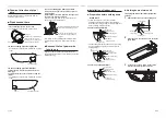
Troubleshooting
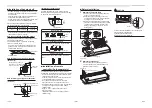
■
Con
fi
rmation and check
When an error occurred in the air conditioner, an error
code and indoor UNIT No. appear on the display part
of the remote controller.
The error code is only displayed during the operation.
If the display disappears, operate the air conditioner
according to the following “Con
fi
rmation of error log”
for con
fi
rmation.
■
Con
fi
rmation of error log
When an error occurred on the air conditioner, the
error log can be con
fi
rmed with the following proce-
dure. (The error log is stored in memory up to 4 er-
rors.) The log can be con
fi
rmed from both operating
status and stop status.
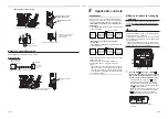
1
When
and
buttons are pushed
simultaneously for 4 seconds or more, the
following display appears.
If is displayed, the mode enters in the error log
mode.
• [
01
: Order of error log] is displayed in CODE No..
• [Error code] is displayed in CHECK.
• [Indoor unit address in which an error occurred]
is displayed in Unit No..
2
Every pushing of
button used to set
temperature, the error log stored in memory is
displayed in order.
The numbers in CODE No. indicate CODE No.
[
01
] (latest)
→
[
04
] (oldest).
REQUIREMENT
Do not push button because all the error log of the
indoor unit will be deleted.
3
After con
fi
rmation, push
button to return to
the usual display.
Error code
Indoor UNIT No. in which
an error occurred
■
Check codes and parts to be checked
Wired
remote
controller
display
Wireless remote
controller Sensor
block display of
receiving unit
Main defective parts
Judging
device
Parts to be checked / error description
Air
conditioner
status
Indication
Operation
Timer
Ready GR
GR OR
Flashing
E01
No header remote controller
Remote
controller
Incorrect remote controller setting --- The header
remote controller has not been set (including two
remote controllers).
*
Remote controller
communication error
No signal can be received from the indoor unit.
E02
Remote controller transmission
error
Remote
controller
System interconnection wires, indoor P.C. board,
remote controller --- No signal can be sent to the
indoor unit.
*
E03
Indoor unit-remote controller
regular communication error
Indoor
Remote controller, network adapter, indoor P.C.
board --- No data is received from the remote
controller or network adapter.
Auto-
reset
E04
Indoor unit-outdoor unit serial
communication error
Indoor
System interconnection wires, indoor P.C. board,
outdoor P.C. board --- Serial communication error
between indoor unit and outdoor unit
Auto-
reset
IPDU-CDB communication error
E08
Duplicated indoor addresses
Indoor
Indoor address setting error --- The same address
as the self-address was detected.
Auto-
reset
E09
Duplicated header remote
controllers
Remote
controller
Remote controller address setting error
--- Two remote controllers are set as header in the
double- remote controller control.
*
(* The header indoor unit stops raising alarm and
follower indoor units continue to operate.)
E11
Indoor unit-optional parts
communication error
Indoor
Communication error between indoor P.C. board
and optional parts
Entire
stop
E18
Header unit follower unit regular
communication error
Indoor
Indoor P.C. board --- Regular communication is
not possible between header and follower indoor
units or between twin header (main) and follower
(sub) units.
Auto-
reset
E31
IPDU communication error
Outdoor Communication error between IPDU and CDB
Entire
stop
F01
ALT Indoor unit heat exchanger
sensor (TCJ) error
Indoor
Heat exchanger sensor (TCJ), indoor P.C.
board --- Open-circuit or short-circuit of the heat
exchanger sensor (TCJ) was detected.
Auto-
reset
F02
ALT Indoor unit heat exchanger
sensor (TC) error
Indoor
Heat exchanger sensor (TC), indoor P.C. board
--- Open-circuit or short-circuit of the heat
exchanger sensor (TC) was detected.
Auto-
reset
F04
ALT Outdoor unit discharge temp.
sensor (TD) error
Outdoor
Outdoor temp. sensor (TD), outdoor P.C. board
--- Open-circuit or short-circuit of the discharge
temp. sensor was detected.
Entire
stop
F06
ALT Outdoor unit temp. sensor (TE/
TS) error
Outdoor
Outdoor temp. sensors (TE/TS), outdoor P.C.
board --- Open-circuit or short-circuit of the heat
exchanger temp. sensor was detected.
Entire
stop
F07
ALT TL sensor error
Outdoor TL sensor may be displaced, disconnected or
short- circuited.
Entire
stop
F08
ALT Outdoor unit outside air temp.
sensor error
Outdoor
Outdoor temp. sensor (TO), outdoor P.C. board
--- Open-circuit or short-circuit of the outdoor air
temp. sensor was detected.
Operation
continued
F10
ALT Indoor unit room temp. sensor
(TA) error
Indoor
Room temp. sensor (TA), indoor P.C. board
--- Open- circuit or short-circuit of the room temp.
sensor (TA) was detected.
Auto-
reset
F12
ALT TS (1) sensor error
Outdoor TS (1) sensor may be displaced, disconnected or
short-circuited.
Entire
stop
F13
ALT Heat sink sensor error
Outdoor Abnormal temperature was detected by the temp.
sensor of the IGBT heat sink.
Entire
stop
F15
ALT Temp. sensor connection error
Outdoor Temp. sensor (TE/TS) may be connected
incorrectly.
Entire
stop
F29
SIM Indoor unit, other P.C. board
error
Indoor
Indoor P.C. board --- EEPROM error”
Auto-
reset
47-EN
48-EN