


Indoor unit
Remote
controller
Indoor unit
Indoor unit
Indoor unit
– 15 –
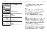
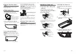
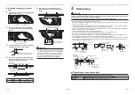
Attached
banding band
Fix it with vinyl tape
Face the incision upward.
Local piping side
Attached heat insulation
pipe
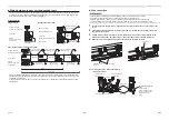
Open the valve fully
Open the valve of the outdoor unit fully. A 4 mm-
hexagonal wrench is required for opening the valve.
For details, refer to the Installation Manual attached
to the outdoor unit.
Gas leak check
Check with a leak detector or soap water whether gas
leaks or not, from the pipe connecting section or cap
of the valve.
REQUIREMENT
Use a leak detector manufactured exclusively for HFC
refrigerant (R32, R134a, R410A, etc.).
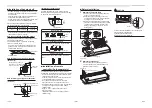
Heat insulation process
Apply heat insulation for the pipes separately at liquid
side and gas side.
• For the heat insulation to the pipes at gas side, use
the material with heat-resisting temperature 120 °C
or higher.
• To use the attached heat insulation pipe, apply the
heat insulation to the pipe connecting section of the
indoor unit securely without gap.
REQUIREMENT
• Apply the heat insulation to the pipe connecting
section of the indoor unit securely up to the root
without exposure of the pipe. (The pipe exposed to
the outside causes water leak.)
• Wrap heat insulator with its slits facing up (ceiling
side).
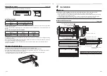
7
Electrical
connection
WARNING
•
Use the speci
fi
ed wires for wiring connect the terminals. Securely
fi
x them to prevent external forces
applied to the terminals from affecting the terminals.
Incomplete connection or
fi
xation may cause a
fi
re or other trouble.
•
Connect earth wire. (grounding work)
Incomplete grounding cause an electric shock.
Do not connect earth wires to gas pipes, water pipes, lightning conductor or telephone earth wires.
• Appliance shall be installed in accordance with national wiring regulations.
Capacity shortage of power circuit or incomplete installation may cause an electric shock or a
fi
re.
CAUTION
• Do not connect 220–240 V power to the terminal blocks (
A
,
B
) for control wiring.
Otherwise, the system will fail.
• Do not damage or scratch the conductive core and inner insulator of power and system interconnection wires
when peeling them.
• Perform the electric wiring so that it does not come to contact with the high-temperature part of the pipe.
The coating may melt resulting in an accident.
• Do not turn on the power of the indoor unit until vacuuming of the refrigerant pipes completes.
■
System interconnection wires speci
fi
cations
•
For power supply speci
fi
cations, follow the Installation Manual of outdoor unit. The power of the indoor
unit is supplied from the outdoor unit.
System
interconnection
wires*
4 x 1.5 mm
2
or more
(H07RN-F or 60245 IEC 66)
Up to 70 m
*Number of wire x wire size
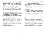
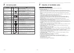
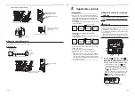
Remote controller wiring
Remote controller wiring, remote controller inter-unit
wiring
Wire size: 2 × 0.5 to 2.0 mm
2
Total wire length of remote controller wiring and remote
controller inter-unit wiring = L + L1 + L2 + … Ln
In case of wired type only
Up to 500 m
In case of wireless type
included
Up to 400 m
Total wire length of remote controller inter-unit wiring = L1 + L2 + … Ln
Up to 200 m
CAUTION
The remote controller wire and system interconnection wires cannot be parallel to contact each other and cannot be
stored in the same conduits. If doing so, a trouble may be caused on the control system due to noise or other factor.
Remote
controller
wiring
Remote controller inter-unit wiring
Ln
(Max. 8 units)
L2
L1
L
29-EN
30-EN