


– 45 –
No.
1
2
3
4
5
6
*
1
*
2
*
3
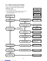
Troubleshooting Procedure
First Confirmation
Primary Judgment
Judgment by Flashing LED of Indoor Unit (Switch Panel)
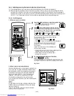
Self-Diagnosis by Remote Controller (Check Code)
Judgment of Trouble by Every Symptom
How to Check Simply the Main Parts
Trouble Diagnosis by Outdoor LED
How to Diagnose Trouble in Outdoor Unit
How to Simply Judge Whether Outdoor Fan Motor is Good or Bad
Page
46
46
47
48
51
54
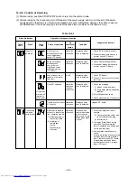
12. HOW TO DIAGNOSE THE TROUBLE
The pulse modulating circuits are mounted to both indoor and outdoor units.
Therefore, diagnose troubles according to the trouble diagnosis procedure as described below.
Table 12-1
NOTE :
A large-capacity electrolytic capacitor is used in the
outdoor unit controller (inverter). Therefore, if the
power supply is turned off, charge (charging voltage
DC280V) remains and discharging takes a lot of time.
After turning off the power source, if touching the
charging section before discharging, an electrical
shock may be caused. Discharge the electrolytic
capacitor completely by using soldering iron, etc.
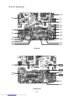
< Discharging method >
(1) Remove the inverter cover (plating) by opening
four mounting claws.
(2) As shown below, connect the discharge resis-
tance (approx. 100
Ω
/40W) or plug of the solder-
ing iron to voltage b – terminals of
electrolytic capacitor on P.C. board, and then
perform discharging. For details, refer to the
service manual of the outdoor unit to be com-
bined.
Fig. 12-1
Discharging position
(Discharging period
10 seconds or more)
Plug of
soldering iron
Inverter cover
P. C. board
(Soldered surface)
*
1,
*
2,
*
3 : For the outdoor unit, refer to the service manual of the outdoor unit to be combined.
Содержание RAS-M10YDCV-E
Страница 62: ......