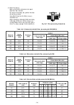


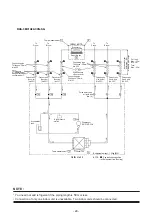


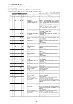

7. REFRIGERANT CYCLE DIAGRAM
NOTE :
•
You need not add refrigerant if the piping length is
30
m or less.
•
Connection of only one indoor unit is unavailable. Two indoor units should be connected.
P
Gauge attaching port
connecting port
Packed valve
(Liquid side)
(dia.6.35)
Sectional shape
of heat insulator
Connecting pipe
Thickness : 0.8mm
dia.9.52
Packed valve
(Gas side)
(dia.9.52)
Packed valve
(Gas side)
(dia.
9.52
)
Connecting pipe
Thickness : 0.8mm
dia.6.35
Packed valve
(Liquid side)
(dia.6.35)
Outdoor unit
Refrigerant amount : 1.00kg (R32)
TO
Propeller fan
T2
Temp.measurement
TD
Compressor
DX136A1T-40N
High pressure
switch
TGa
TGb
To
B room
To
B room
Allowable height difference : 10m
Allowable pipe length
Per 1 unit
Max. : 20m
Min. : 2m
Total
Max. : 30m
Cross flow fan
TA
Indoor unit A
T1
Temp. measurement
TC
Evaporator
RAS-2M2
1
U2ACVG-SG
NOTE :
Gas leak check position
Refrigerant flow (Cooling)
Pressure
measurement
7-1. Refrigerant Cycle Diagram
- 28 -
Содержание RAS-2M21U2ACVG-SG
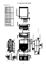
Страница 24: ...Outdoor Unit 4 CONSTRUCTION VIEWS Unit mm RAS 3M31U2ACVG SG RAS 3M41U2ACVG SG RAS 2M21U2ACVG SG 24 ...
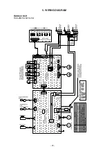
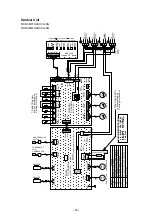
Страница 25: ...5 WIRING DIAGRAM Outdoor Unit RAS 2M21U2ACVG SG t t t t t t 25 ...
Страница 91: ...144 9 MOO 5 BANGKADI INDUSTRIAL PARK TIVANON ROAD TAMBOL BANGKADI AMPHUR MUANG PATHUMTHANI 12000 THAILAND ...