


–
62
–
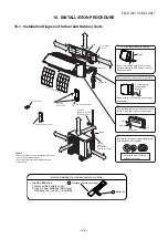
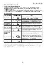
10. INSTALLATION PROCEDURE
10-1. Installation Diagram of Indoor and Outdoor Units
FILE NO. SVM-1
401
7
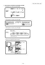
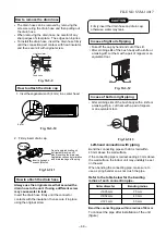
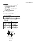
Before installing the wireless remote controller
•
Loading Batteries
1. Remove the battery cover.
2. Insert 2 new batteries (AAA type)
following the (+) and (- ) positions.
3 Batteries
2 Wireless remote controller
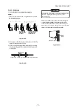
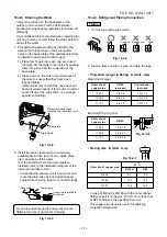
Insulate the refrigerant pipes separately
with insulation, not together.
2
3
6
4
Insert the cushion between the indoor
unit and wall, and tilt the indoor unit for
better operation.
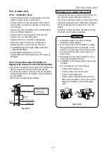
For the rear left and left piping
Wall
Make sure to run the drain hose sloped
downward.
Do not allow the drain hose to get slack.
Cut the piping
hole sloped
slightly.
The auxiliary piping can be connected to
the left, rear right, right or bottom right.
Right
Rear right
Bottom right
Left
1
Batteries
Flat head
wood screw
Remote control holder
Vinyl tape
Apply after carrying
out a drainage test.
Wireless remote control
Saddle
Extension
drain hose
(Not available,
provided by installer)
Shield pipe
(Attach to the front panel.)
Air f lter
Hook
Installation
plate
Hook
52 mm or more
190 mm or more
225 mm or more
600 mm or more
100 mm or more
100 mm or more
600 mm or more
600 mm or more
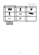
Remark :
• Detail of accessory and installation parts can
see in the accessory sheet.
• Some pictures might be different from the
actual parts.
6 mm thick heat resisting
polyethylene foam
Bush body
Содержание RAS-25G2AVP-ND
Страница 18: ... 17 5 WIRING DIAGRAM FILE NO SVM 14017 ...
Страница 127: ... 56 FILE NO SVM 03005 TOSHIBA CARRIER THAILAND CO LTD ...