


–
30
–
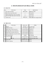
Item
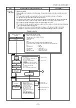
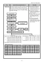
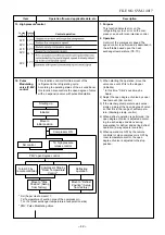
2. Indoor fan
motor control
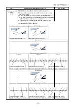
Operation flow and applicable data, etc.
<In heating operation>
Description
1) When setting the fan speed to L,
L+, M, M+, H or Quiet on the remote
controller, the operation is per-
formed with the constant speed
shown in Fig. 3 and Table 1.
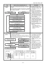
2) When setting the fan speed to
AUTO on the remote controller,
revolution of the fan motor is
controlled to the fan speed level
shown in Fig. 5 according to the set
temperature and room temperature.
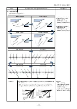
3) Min air flow rate is controlled by
temperature of the indoor heat
exchanger (Tc) as shown in Fig. 4.
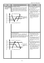
4) Cold draft prevention, the fan
speed is controlled by temperature
of the indoor heat exchanger (Tc)
as shown in Fig. 6.
In starting
In stability
Until 12 minutes passed after operation start
When 12 to 25 minutes passed after operation
start and room temp
erature
is 3°C or lower than
set temp
erature.
•
When 12 to 25 minutes
passed
after operation start
and room temp
erature
is
higher than
(set
temp
erature
–3°C)
FAN AUTO
•
When 25 minutes or more passed after operation start
FAN Manual
•
Room
temp
erature
< Set
temp
erature
–4°C
•
Room temp
erature
≥
Set temp
erature
–3.5°C
•
•
(Fig. 3)
(Fig. 4)
Cold draft preventive control
(Fig. 6)
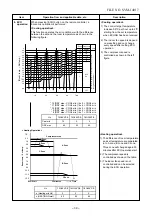
Fan speed
AUTO
Basic fan control
* No limitation while fan speed MANUAL mode is in stability.
* A: When Tsc
≥
24, A is 24, and when Tsc < 24, A is Tsc
Tsc: Set value
TSC
TA
[°C]
b
–0.5
c
–1.0
d
–1.5
e
–2.0
f
–2.5
g
–5.0
–5.5
L+ (W9)
*1
*2
*3
H (WE)
H (WE)
Line-approximate
H and SUL with Tc.
SUL (W2)
Stop
45
Tc
33
44
32
33
21
32
20
*A+4
*A+4
*A-4
*A-8
Fan speed MANUAL in starting
Fan speed AUTO in stability a
nd
stability
L
L+
M
M+
H
W8
(L + M) / 2
WB
(M + H) / 2
WE
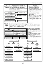
Indication
Fan speed
Fan speed setup
HEAT ON
AUTO
YES
NO
MANUAL
TC
≥
42°C
W
Min air flow rate control
Tc
51
50
42
41
M+ (WC)
* Fan speed =
(TC – (41+a)) / (5
1
−
41) x (M+
−
L
) + L
No limit
*
*1: Fan speed = (M + -L+) x 1
5
+ L+
*2: Fan speed = (M + -L+) x 2
5
+ L+
*3: Fan speed = (M + -L+) x 3
5
+ L+
(Calculated with linear approximation from M+ and L+)
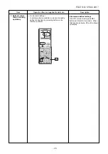
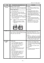
5) In order to prevent Cold draft when
compressor step during heating
operation. Then louver will move to
upper position and fan speed will
reduce or off.
FILE NO. SVM-1
401
7
Quiet
5
*
4
4
: Fan speed = (M + -L+) x
4
5
+ L+
*
(Fig. 5)
[[In starting and in stability]
Содержание RAS-25G2AVP-ND
Страница 18: ... 17 5 WIRING DIAGRAM FILE NO SVM 14017 ...
Страница 127: ... 56 FILE NO SVM 03005 TOSHIBA CARRIER THAILAND CO LTD ...