


–
19
–
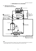
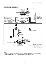
7. REFRIGERANT CYCLE DIAGRAM
7-1. Refrigerant Cycle Diagram
FILE NO. SVM-14017
NOTE :
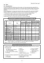
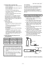
• The maximum pipe length of this air conditioner is 25 m. When the pipe length exceeds 15m, the additional
Max. : 2
5
m
Deoxidized copper pipe
NOTE :
Gas leak check position
Refrigerant flow (Cooling)
Refrigerant flow (Heating)
INDOOR UNIT
T1
TO
Temp. measurement
Indoor heat
exchanger
Cross flow fan
Deoxidized copper pipe
Outer dia. : 6.35mm
Thickness : 0.8mm
Sectional shape
of heat insulator
Allo
w
ab
le height
diff
erence :
10m
Allo
w
ab
le pipe length
P
Pressure measurement
Gauge attaching port
Vacuum pump connecting port
Pulse Modulating
valve at liquid side
Ø1.2 x 80
Ø1.2 x 80
TD
4-way valve
Compressor
DA111A1F-24F
TS
T2
Outdoor heat
exchanger
Split capillary
Temp. measurement
Propeller fan Refrigerant amount :
1.05
kg
OUTDOOR UNIT
Muffler
Muffler
TE
TC
TA
Min. :
2
m
Chargeless : 15m
Charge : 20g/m
(16 to 2
5
m)
charging of refrigerant, 20g per 1m for the part of pipe exceeded 15m is required. (Max. 200g)
Tcj
Outer dia. : 9.52mm
Thickness : 0.8mm
RAS-10G2KVP-E / RAS-10G2AVP-E
Содержание RAS-25G2AVP-ND
Страница 18: ... 17 5 WIRING DIAGRAM FILE NO SVM 14017 ...
Страница 127: ... 56 FILE NO SVM 03005 TOSHIBA CARRIER THAILAND CO LTD ...