

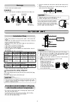


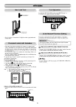


Flat head
wood screw
Remote control
holder
Wireless
remote control
2
7
4
1
3
5
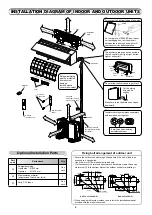
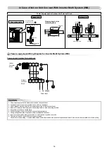
INSTALLATION DIAGRAM OF INDOOR AND OUTDOOR UNITS
Part
code
Parts name
Q’ty
A
Refrigerant piping
Liquid side : Ø6.35 mm
Gas side
: Ø12.70 mm
One
each
B
Pipe insulating material
(polyethylene foam, 8 mm thick)
1
C
Putty, PVC tapes
One
each
Optional Installation Parts
Secure the outdoor unit with fi xing bolts and nuts if the unit is likely to be
exposed to a strong wind.
Use Ø8 mm or Ø10 mm anchor bolts and nuts.
If it is necessary to drain the defrost water, attach drain nipple
#
and cap
water proof
$
to the bottom plate of the outdoor unit before installing it.
When using a multi-system outdoor unit, refer to the installation manual
provided with the model concerned.
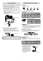
Fixing bolt arrangement of outdoor unit
The auxiliary piping can be connected to
the left, rear left, rear right, right, bottom
right or bottom left.
Right
Rear
right
Bottom
right
Rear
left
Bottom left
Left
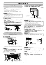
Insulate the refrigerant pipes separately
with insulation, not together.
8 mm thick heat resisting
polyethylene foam
Batteries
Vinyl tape
Apply after carrying
out a drainage test.
Saddle
Extension drain hose
(Not available, provided
by installer)
Shield pipe
(Attach to the front panel.)
Air fi lter
Hook
Installation
plate
Hook
50 mm or more
300 mm or more
170 mm or more
er
o
m r
o
m
m
00
6
100 mm or more
100 mm or more
600 mm or more
600 mm or more
E1
-
G
S
V
A
2
J
4
2
-
S
A
R
E1
-
G
S
V
A
2
J
2
2
,
8
1
-
S
A
R
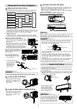
Cut out a piece of SPACER from indoor
unit packaging box, roll it and insert
between the indoor unit and wall to tilt
the indoor unit for better operation.
For the rear left, bottom left and left piping
Wall
Make sure to run the drain hose sloped
downward.
Do not allow the drain hose to get slack.
Cut the piping
hole sloped
slightly.
Refrigerant piping
must be protected
from physical
damage.
Install a plastic
cover or equivalent.
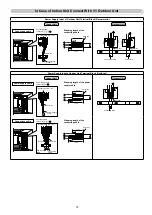
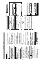
Filter
125 mm
108 mm
28 mm
340 mm
600 mm
90 mm
Drain outlet
86 mm
102 mm
Air outlet
Air inlet
125 mm
108 mm
29 mm
350 mm
600 mm
99 mm
106 mm
121 mm
Air outlet
Air inlet
Drain outlet
320 mm
330 mm
6
Содержание RAS-18J2AVSG-E1
Страница 20: ...18 ...