


4
5
45º
45º
75º
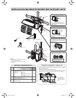
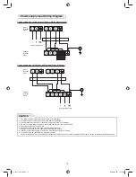
Installation plate
(Keep horizontal direction.)
Anchor bolt
Projection
15 mm or less
5 mm dia. hole
Mounting screw
Ø4 x 25
R
Clip anchor
(local parts)
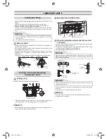
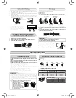
INDOOR UNIT
INDOOR UNIT
Installation Place
• Direct sunlight to the indoor unit’s wireless receiver should be avoided.
• The microprocessor in the indoor unit should not be too close to RF
noise sources.
(For details, see the owner’s manual.)
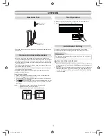
Remote control
• A place where there are no obstacles such as a curtain that may block the
signal from the indoor unit
• Do not install the remote control in a place exposed to direct sunlight or close
to a heating source such as a stove.
• Keep the remote control at least 1 m apart from the nearest TV set or stereo
equipment. (This is necessary to prevent image disturbances or noise
interference.)
• The location of the remote control should be determined as shown below.
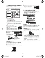
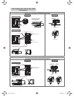
Cutting a Hole and Mounting
Installation Plate
NOTE
• When drilling a wall that contains a metal lath, wire lath or metal plate, be sure
to use a pipe hole brim ring sold separately.
Cutting a hole
When installing the refrigerant pipes from the rear
Mounting the installation plate
When the installation plate is directly mounted
on the wall
1. Securely
fi
t the installation plate onto the wall by screwing it in the upper and
lower parts to hook up the indoor unit.
2. To mount the installation plate on a concrete wall with anchor bolts, use the
anchor bolt holes as illustrated in the below
fi
gure.
3. Install the installation plate horizontally in the wall.
When installing the installation plate with a mounting screw, do not use the
anchor bolt holes. Otherwise, the unit may fall down and result in personal
injury and property damage.
1. After determining the pipe hole position on the mounting plate (
¨
), drill the
pipe hole (Ø65 mm) at a slight downward slant to the outdoor side.
• A place which provides the spaces around the indoor unit as shown in the
diagram
• A place where there are no obstacles near the air inlet and outlet
• A place which allows easy installation of the piping to the outdoor unit
• A place which allows the front panel to be opened
• The indoor unit shall be installed as top of the indoor unit comes to at least
2 m height. Also, it must be avoided to put anything on the top of the indoor
unit.
CAUTION
CAUTION
Failure to
fi
rmly install the unit may result in personal injury and property
damage if the unit falls.
• In case of block, brick, concrete or similar type walls, make 5 mm dia. holes
in the wall.
• Insert clip anchors for appropriate mounting screws
5
.
NOTE
• Secure four corners and lower parts of the installation plate with 4 to 6
mounting screws to install it.
CAUTION
(Side view)
(Top view)
Indoor unit
Reception range
Remote
control
Remote
control
Reception
range
Indoor unit
The center of the pipe
hole is above the arrow.
35
Ø
65
1
5
Anchor bolt holes
Hook
Hook
Hook
Pipe hole
Pipe hole
Installation
plate
Mounting screw
Weight
Indoor unit
Thread
2 m or more from
fl
oor
52
40
190
104
225
137
1115751104-EN.indd 4
1115751104-EN.indd 4
5/26/2557 BE 10:45 AM
5/26/2557 BE 10:45 AM