


8
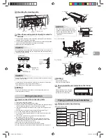
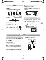
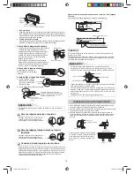
Stripping length of the Power supply cord and
Interconnecting cable
L
1
L
2
L
1
L
2
S
Interconnecting cable
Power supply cord
Terminal block
Unit : inch (mm)
L
1
L
2
L
1
L
2
S
Ground line
Connecting cable
Power cord
Ground line
3/8 (10)
3/8 (10)
1-3/16 (30)
2-12/16 (70)
3/8 (10)
3/8 (10)
1-3/16 (30)
1-9/16 (40)
Conduit plate
Connector
Lock nut
Valve cover
NOTE
: Interconnecting cable
• Wire type : minimum AWG14
CAUTION
• Wrong wiring connection may cause some electrical parts to fail.
• Be sure to comply with LOCAL CODES.
• Every wire must be connected
fi
rmly.
• If incorrect or incomplete wiring is carried out, it could cause an
ignition or smoke.
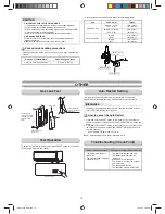
INDOOR UNIT
INDOOR UNIT
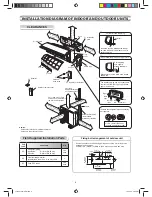
Installation Location
• Direct sunlight to the indoor unit’s wireless receiver should be avoided.
• The microprocessor in the indoor unit should not be too close to RF
noise sources.
(For details, see the owner’s manual.)
NOTE
• When drilling a wall that contains a metal lath, wire lath or metal plate, be
sure to use a hole saw.
After determining the pipe hole position on the mounting plate (
➡
), drill the
pipe hole Ø2-9/16 in. (Ø65 mm) at a slight downward slant to the outdoor
side.
• A location which provides the clearances around the indoor unit as shown
in the diagram in the “CLEARANCES” section.
• A location where there are no obstacles near the air inlet and outlet
• A location which allows easy installation of the piping to the outdoor unit
• A location which allows the front panel to be opened
• The indoor unit shall be installed such that the top of the indoor unit
comes to at least 6.6 ft (2 m) height. Also avoid putting anything on the top
of the indoor unit.
• A location that will bear the weight of the unit.
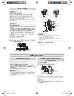
CAUTION
Cutting a hole
When installing the refrigerant pipes from the rear
80
100
180
The center of the pipe
hole is above the arrow.
Pipe hole
Ø2-9/16 in. (65 mm)
3-15/16 in.
(100 mm)
Cutting a Hole and Mounting the
mounting Plate
1. The supply voltage must be the same as the rated voltage of the air
conditioner.
2. Prepare the power source for exclusive use with the air conditioner.
NOTE
: Power supply cord
• Wire type : minimum AWG14
CAUTION
UNIT DAMAGE HAZARD
Failure to follow this caution may result in equipment damage or improper
operation.
Unit failure as a result or of improper line voltage application or excessive
phase imbalance constitutes abuse and may cause damage to electrical
components. Such operation could void any applicable warranty.
Electrical Work
WARNING
ELECTRICAL SHOCK HAZARD
Failure to follow this warning could result in personal injury or death.
The unit cabinet must have an uninterrupted or unbroken ground
to minimize personal injury if an electrical fault should occur. The
ground may consist of electrical wire or metal conduit when installed in
accordance with existing electrical codes.
Make sure main power switch is turned OFF before performing service or
maintenance.
1110251291-2 EN.indd 8
1110251291-2 EN.indd 8
12/13/13 5:00 PM
12/13/13 5:00 PM
Содержание RAS-09 12EA Series
Страница 39: ...1110251291 2 FR indd 13 1110251291 2 FR indd 13 12 17 13 5 03 PM 12 17 13 5 03 PM ...
Страница 40: ...1110251291 2 FR indd 14 1110251291 2 FR indd 14 12 17 13 5 03 PM 12 17 13 5 03 PM ...
Страница 79: ...1110651824 2 FR indd 13 1110651824 2 FR indd 13 12 17 13 2 15 PM 12 17 13 2 15 PM ...
Страница 80: ...1110651824 2 FR indd 14 1110651824 2 FR indd 14 12 17 13 2 15 PM 12 17 13 2 15 PM ...