


– 39 –
▼
Power supply
Control wiring, Central controller wiring
• 2-core with polarity wires are used for the Control wiring between indoor unit and outdoor unit and Central
controller wiring.
• To prevent noise trouble, use 2-core shield wire.
• The length of the communication line means the total length of the inter-unit wire length between indoor and
outdoor units added with the central control system wire length.
▼
Communication line
Remote controller wiring
• 2-core with non-polarity wire is used for wiring of the remote controller wiring and group remote controllers wiring.
CAUTION
The remote controller wire (Communication line) and AC 220-240 V wires cannot be parallel to contact
each other and cannot be stored in the same conduits. If doing so, a trouble may be caused on the control
system due to noise or other factor.
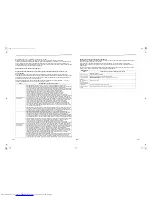
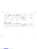
Power supply
220-240 V ~, 50 Hz
220 V ~, 60 Hz
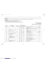
Power supply switch / circuit breaker or power supply wiring / fuse rating for indoor units should be selected by the
accumulated total current values of the indoor units.
Power supply wiring
Below 50 m
2.5 mm
2
Control wiring between indoor units, and
outdoor unit (2-core shield wire)
Wire size
(Up to 1000 m) 1.25 mm²
(Up to 2000 m) 2.0 mm²
Central control line wiring (2-core shield
wire)
Wire size
(Up to 1000 m) 1.25 mm²
(Up to 2000 m) 2.0 mm²
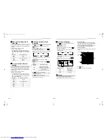
Remote controller wiring, remote controller inter-unit
wiring
Wire size: 0.5 mm² to 2.0 mm²
Total wire length of remote controller wiring and remote
controller inter-unit wiring = L + L1 + L2 + … Ln
In case of wired type only
Up to 500 m
In case of wireless type
included
Up to 400 m
Total wire length of remote controller inter-unit wiring = L1 + L2 + … Ln
Up to 200 m
L1
L
L2
Ln
Indoor unit
Remote controller inter-unit wiring
Indoor unit
Indoor unit
Indoor unit
Remote
controller
(Max. 8 units)
Remote
controller
wiring
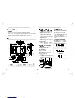
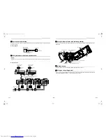
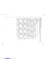
Wire connection
REQUIREMENT
• Be sure to connect the wires matching the terminal numbers. Incorrect connection causes a trouble.
• Be sure to pass the wires through the bushing of wiring connection port of the indoor unit.
• Keep a margin (Approx. 100 mm) on a wire to hang down the electrical control box at servicing, etc.
• The low-voltage circuit is provided for the remote controller. (Do not connect the high-voltage circuit)
• Make a loop on the wire for margin of the length so that the electrical control box can be taken out during servicing.
1. Remove the cover of the electrical control box by taking off the mounting screws (2 positions) and pushing the
hooking section. (The cover of the electrical control box remains hanged to the hinge.)
2. Connect the power supply wire and remote controller wire to the terminal block of the electrical control box.
3. Tighten the screws of the terminal block, and fix the wires with cord clamp attached to the electrical control box. (Do
not apply tension to the connecting section of the terminal block.)
4. Using the attached heat insulation material, seal the pipe connecting port. Otherwise, dewing may be caused.
5. Mount the cover of the electrical control box without pinching wires.
(Mount the cover after wiring on the ceiling panel.)
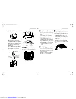
L
N
U
1
U
2
A
B
R
(L)
10
10
50
70
S
(N)
Hinge
Screws in 2 positions
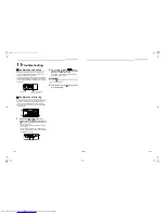
Louver connector
(CN510: White)
Side D (Space: 8.5 mm)
Side C (Space: 4 mm)
* Cable clamp can be attached on left side.
Wire
type
Specification
Cable clamping
position
Cabtyre
cable
3-core stranded
wire 2.5 mm²
Side D
Cabtyre
cable
4-core stranded
wire 1.5 mm²
Side C
Adhered surface
Notched section
▼
Heat insulation to wiring
connecting port
Power supply terminal block
Indoor / Outdoor
inter-unit wire /
Remote
controller
terminal block
Cord clamp
Earth wire
Power supply wire
77-EN
78-EN
+001114119501.book Page 39 Wednesday, October 17, 2012 8:23 PM