


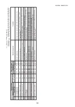


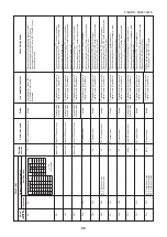


48
(
∗
)
¡
: Goes on,
¥
: Flashes
,
l
: Goes off
A
(Alter
nate)
: Flashing condition is alter
nate when there are tw
o flashing LED
.
S (Sim
ultaneously)
: T
w
o LED flash sim
ultaneously when there are tw
o flashing LED
.
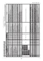
Chec
k code displa
y
TCC-LINK central & remote contr
oller
s
H05
H15
H25
H06
H07
H08
H16
L04
L05
L06
L08
L10
L17
L18
L26
L27
L28
L29
(L30)
P03
P05
Sensor lamp displa
y
Bloc
k displa
y
Oper
ation
Timer
Ready
Flash
l
¥
l
l
¥
l
l
¥
l
l
¥
l
l
¥
l
l
¥
l
l
¥
l
¥¡
¥
S
¥
l
¥
S
¥
l
¥
S
¥
l
¥
S
¥¡
¥
S
¥¡
¥
S
¥¡
¥
S
¥¡
¥
S
¥¡
¥
S
¥¡
¥
S
¥¡
¥
S
¥¡
¥
S
¥
l
¥
A
¥
l
¥
A
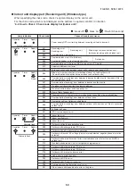
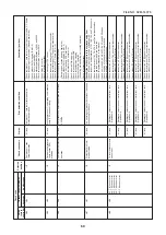
Outdoor 7-segment
A
uxiliar
y code
H05
—
H15
—
H25
—
H06
—
H07
—
01
:TK1 sensor error
02
:TK2 sensor error
H08
03
:TK3 sensor error
04
:TK4 sensor error
05
:TK5 sensor error
01
:TK1 Oil circuit system error
02
:TK2 Oil circuit system error
H16
03
:TK3 Oil circuit system error
04
:TK4 Oil circuit system error
05
:TK5 Oil circuit system error
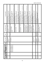
L04
—
L06
No
. of preceded indoor units
([L05/L06] b
y individual displa
y)
L08
—
L10
—
L17
—
L18
—
L26
No
. of connected heat units
L27
No
. of connected heat units
L28
—
L29
L30
Detection of indoor unit n
umber
P03
—
00
:Open phase shor
tage detection
P05
01
:Compressor 1 side
02
:Compressor 2 side
03
:Compressor 3 side
Main def
ective position
Outdoor discharge temp
. sensor (TD1)
mis
wir
ing
Outdoor discharge temp
. sensor (TD2)
mis
wir
ing
Outdoor discharge temp
. sensor (TD3)
mis
wir
ing
Lo
w pressure protectiv
e oper
ation
Protection f
or oil le
vel drop
Oil le
vel detection temp
. sensor
(TK1 to 5) error
Detection circuit error
Duplicated outdoor system address
Duplicated pr
ior
ity indoor units
(Displa
yed in pr
ior
ity indoor unit)
Duplicated pr
ior
ity indoor units
(Displa
yed e
xcept pr
ior
ity indoor unit)
Unset indoor g
roup address
Unset outdoor unit capacity
Disag
reed error of outdoor model
Refr
iger
ant change unit system error
No
. of connected heat unit o
ver
No
. of connected heat unit error
No
. of connected outdoor units o
ver
IPDU quantity error
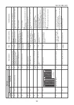
Outside error input in indoor (Inter
loc
k)
Outdoor unit discharge (TD1) temp
. error
Open phase shor
tage:
P
ow
er f
ailure error
In
ve
rter DC v
oltage (Vdc) error
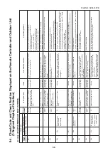
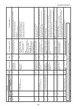
Description
Mis
wir
ing or mismounting of outdoor discharge temp
. sensor (TD1) or coming-out
of
TD1 sensor w
as detected.
Mis
wir
ing or mismounting of outdoor discharge temp
. sensor (TD2) or coming-out
of
TD2 sensor w
as detected.
Mis
wir
ing or mismounting of outdoor discharge temp
. sensor (TD3) or coming-out
of
TD3 sensor w
as detected.
Protection b
y lo
w pressure (Ps) sensor w
as detected.
Protection detection b
y temp
. sensor (TK1 to 5) f
or oil le
vel detection.
Open/Shor
t of temp
. sensor (TK1 to 5) f
or oil le
vel detection w
as detected.
After star
ting compressor oper
ation, temper
ature change of temp
. sensor
(TK1 to 5) f
or oil le
vel detection w
as not detected.
Duplicated setting of system address to outdoor units of diff
erent refr
iger
ant
piping system
Duplicated pr
ior
ity indoor units (F
or pr
ior
ity indoor unit)
Duplicated pr
ior
ity indoor units (F
or indoor units without pr
ior
ity)
There is indoor unit which indoor g
roup address w
as not set
(Detected also at indoor unit side)
Capacity of outdoor unit is not set.
(Exchange ser
vice P
.C
. board.)
Fo
rmer model of outdoor unit (Bef
ore 3 ser
ies) w
as connected.
COOL/HEA
T cycle error b
y mispiping, etc w
as detected.
There are 3 or more connected heat units
.
Heat unit w
as not connected, or combination of No
. of outdoor units with No
. of
heat units def
ectiv
e.
No
. of connected outdoor units e
xceeded 4 units
N
o.
of IPDU (P
.C
. board) in in
ve
rter bo
x is f
ew
.
There is indoor unit which abnor
mally stops b
y outer error input in 1 system.
(
←
Indoor unit detected.)
High temp
. error w
as detected at outdoor discharge temp
. sensor (TD1).
When pow
er supply w
as tur
ned on, open phase shor
tage w
as detected.
Ov
er current/Current shor
tage w
as detected at in
ve
rter DC v
oltage
.
A3-IPDU
FA
N
A3-IPDU
FA
N
123
IPDU
12
3
IPDU
01
¡
0A
¡¡
02
¡
0B
¡¡
¡
03
¡¡
0C
¡¡
04
¡
0D
¡¡
¡
05
¡¡
0E
¡¡
¡
06
¡¡
0F
¡¡¡
¡
07
¡¡¡
08
¡¡
mar
k:
09
¡¡
Error position.
FILE NO. SVM-1
40
7
8