


17
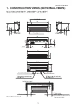
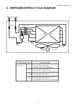
4. REFRIGERANTING CYCLE DIAGRAM
Liquid side Gas side
Strainer
Capillary tube
Air heat exchanger
at indoor side
Strainer
Fan
Fan motor
Sensor
(TCJ)
Sensor
(TC2)
Sensor
(TC1)
Sensor
M
(TA)
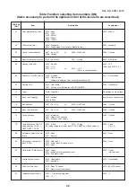
Functional part name
Temp. sensor
1. TA
2. TC1
3. TC2
4. TCJ
Functional outline
(Connector CN104 (2P): White)
1) Detects indoor suction temperature
(Connector CN100 (3P): Brown)
1) Controls PMV super heat in cooling operation
(Connector CN101 (2P): Blue)
1) Controls PMV under cool in heating operation
(Connector CN102 (2P): Yellow)
1) Controls PMV super heat in cooling operation
FILE NO. SVM-1
40
7
8