


33
n
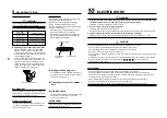
Power supply wire and communication wires specifications
Power supply wire and communication wires are procured locally.
For the power supply specifications, follow the table below. Power supply wiring and communication wiring
are to be procured locally.
For specifications of the power capacity of the outdoor unit and the power supply wires, refer to the
Installation Manual supplied with the outdoor unit.
Indoor unit power supply
• Prepare an exclusive power supply for the indoor unit independently of the outdoor unit.
• Arrange the power supplies to the indoor and outdoor units, so that a common earth leakage breaker and
main switch can be used.
• Power supply wire specification: Cable 3-core 2.5mm², in conformity with Design H07 RN-F or 60245 IEC 57.
u
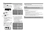
Power supply
Power supply
220–240V ~ 50Hz
220–
220V ~ 60Hz
Power supply switch/Earth leakage breaker or power supply wiring/fuse rating for indoor units should be selected by the
accummulated total current values of the indoor units.
Power supply wiring
Below 50m
2.5 mm²
Control wiring, Central controller wiring
• Use a 2 core non polarity wire.
• To prevent any possible noise issues, use a shielded 2 core wire.
• The total stated length of communication wiring is determined by the interconnecting length of indoor to
outdoor wire plus the length of the central control communication wire.
u
Communication line
Control wiring between indoor units, and outdoor unit
Wire size
(Up to 1000m) 1.25 mm²
(2-core shield wire)
(Up to 2000m) 2.0 mm²
Central control line wiring (2-core shield wire)
Wire size
(Up to 1000m) 1.25 mm²
(Up to 2000m) 2.0 mm²
Wired remote controller wiring
This wiring is not required when using the supplied wireless remote controller.
• For wiring remote controllers a 2 core non polarity wire must be used.
Wired remote controller wiring, remote controller inter-unit wiring
Wire size: 0.5mm² to 2.0mm²
Total wire length of wired remote controller wiring and
In case of wired type only
Up to 500m
remote controller inter-unit wiring = L + L1 + L2 + … Ln
In case of wireless type included
Up to 400m
Total wire length of wired remote controller inter-unit wiring = L1 + L2 + … Ln
Up to 200m
CAUTION
The remote controller wire (Communication line) and AC220–240V wires cannot be parallel to contact each
other and cannot be stored in the same conduits. If doing so, a trouble may be caused on the control system
due to noise, etc.
n
Control wiring between indoor and outdoor units
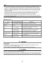
NOTE
An outdoor unit that is interconnected to the indoor units automatically becomes the header unit.
u
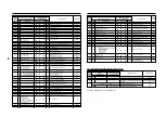
Wiring example
n
Address setup
Set up the addresses as per the Installation Manual supplied with the outdoor unit.
Wired remote controller wiring
Indoor unit
Wired remote controller
L1
L2
Ln
(Max. 8 units)
Remote controller inter-unit wiring
Indoor unit
Indoor unit
Indoor unit
Earth leakage
breaker
A
U2
U1
B
L N
Earth
Indoor unit
A
U2
U1
B
L N
A B
Earth
Remote controller
Indoor unit
A
U2
U1
B
L N
Earth
Indoor unit
A
U2
U1
B
U2 U3 U4 U5 U6
U1
U2 U3
U1
N
L N
Earth
Indoor unit
A B
Remote controller
A B
Remote controller
Pull box
Pull box
Pull box
Earth leakage breaker
power switch
Indoor power supply
220-240V, ~, 50Hz
220V ~, 60Hz
Control wiring between indoor units
Control wiring between indoor and outdoor units
Control wiring between outdoor units
Earth
terminal
Header outdoor unit
Outdoor Power supply
380V-415V ~, 50Hz
380V ~, 60Hz
Earth leakage
breaker
U2 U3 U4 U5 U6
U1
U2 U3
U1
N
Earth
terminal
Follower outdoor unit
Outdoor Power supply
380V-415V ~, 50Hz
380V ~, 60Hz
10
ELECTRIC WORK