


– 24 –
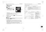
SMMS Concealed Duct High Static Pressure Type
Installation Manual
EN
SMMS Concealed Duct High Static Pressure Type
Installation Manual
C
o
n
firmatio
n
o
f i
ndo
or
un
it setup
Pr
ior
to de
liver
y to th
e custom
er
, check the
add
ress an
d setu
p
of t
he indo
or
unit, which has b
een
insta
lled
in this time
and
fill the
check shee
t (Tab
le
below).
Data
of f
our
units
ca
n be
en
tere
d in
this check she
e
t.
Cop
y this
shee
t accor
d
ing
to
the No.
of t
he ind
oor
un
its.
If th
e install
ed sys
te
m
is
a
group
control
system,
use
this sheet
by ente
ring
each line system into e
a
ch in
stallation
manu
al atta
ch
ed to
the o
ther indo
or u
n
its.
REQUIREMENT
This ch
eck
sheet is
requ
ired for
m
ain
tena
nc
e after insta
llation.
Fill
th
is
sheet and then
pas
s
this
Install
ati
o
n M
anual to th
e
cu
stom
er
s.
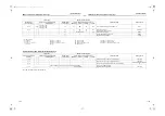
Indo
or
un
it setu
p
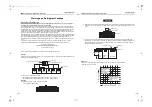
check sheet
Indoor
unit
Indoor uni
t
Indoor unit
Indoo
r
unit
Room
name
Ro
om name
Room name
Room
name
Model
M
odel
M
odel
M
odel
Chec
k indoor u
nit
a
ddres
s.
(For
c
heck method, refer t
o
APPLIC
ABLE CO
NTROLS
in t
his man
ual
.)
*In
case
of a
single s
ystem, it is
unneces
sa
ry
to en
ter
the
in
d
oor
addr
ess. (
C
ODE NO.:
Li
n
e [12], Ind
oor [1
3],
Gr
oup [14], Cent
ral c
ontr
ol [03])
Line
Indoor
Group
Li
ne
Indoor
Group
Line
Indoor
G
roup
Li
ne
Indoor
Group
C
e
nt
ral cont
rol address
Cent
ral
cont
rol
addre
ss
C
entral control address
Cent
ra
l cont
rol
address
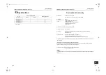
Various set
up
Vari
ous setup
Various
se
tu
p
V
arious set
up
Have
you
cha
nged
lighti
ng
ti
m
e
of
filter
s
ign?
If not, fill
check
m
ark [×] i
n
[N
O CH
ANGE
], a
nd fil
l c
heck
mar
k [×] in
[ITEM]
if ch
anged, r
espec
tively.
(F
or check
m
eth
od, re
fer
to A
PPL
ICABLE CONTR
O
LS
in
thi
s m
anual.)
Fi
lter
s
ign
li
gh
ting
time
(C
OD
E NO
. [
01])
F
NO
CH
A
N
G
E
F
N
O
NE
[0000
]
F
150H
[0001
]
F
2500H
[0002
]
F
5000H
[0003
]
F
10000H
[0004
]
Fil
ter sign
lighti
ng ti
m
e
(C
ODE NO.
[01]
)
F
NO
CHAN
G
E
F
NO
NE
[0
000]
F
150H
[0
001]
F
2500H
[0
002]
F
5000H
[0
003]
F
10000
H
[0
004]
Filter
sign
lighting time
(CO
D
E N
O.
[01])
F
NO CHANG
E
F
NONE
[0000]
F
15
0H
[0001]
F
25
00H
[0002]
F
50
00H
[0003]
F
10
000H
[0004]
F
ilter
s
ign
ligh
tin
g t
im
e
(C
O
D
E N
O
. [01
])
F
N
O
CH
ANGE
F
N
O
NE
[000
0]
F
150H
[000
1]
F
2500H
[000
2]
F
5000H
[000
3]
F
10000H
[000
4]
Have
you
cha
nged
detecte
d tem
p.
shift v
alu
e
? If
not,
fill
chec
k m
ark
[×] in
[NO CHA
NGE], and fil
l check m
ark [×] i
n [ITEM
] i
f c
hanged, respe
ctively.
(F
or check
m
eth
od, re
fer
to A
PPL
ICABLE CONTR
O
LS
in
thi
s m
anual.)
Dete
cted
te
mp
.
shift
va
lue
set
up
(C
OD
E NO
. [
06])
F
NO
CH
A
N
G
E
F
N
O
SH
IFT
[0000
]
F
+1°C
[0001
]
F
+2°C
[0002
]
F
+3°C
[0003
]
F
+4°C
[0004
]
F
+5°C
[0005
]
F
+6°C
[0006
]
D
et
ect
ed
te
m
p. shi
ft val
ue
se
tup
(C
ODE NO.
[06]
)
F
NO
CHAN
G
E
F
NO
SHI
F
T
[0
000]
F
+1°
C
[0
001]
F
+2°
C
[0
002]
F
+3°
C
[0
003]
F
+4°
C
[0
004]
F
+5°
C
[0
005]
F
+6°
C
[0
006]
D
e
tected te
mp.
sh
ift value setup
(CO
D
E N
O.
[06])
F
NO CHANG
E
F
NO SHIFT
[0000]
F
+1
°C
[0001]
F
+2
°C
[0002]
F
+3
°C
[0003]
F
+4
°C
[0004]
F
+5
°C
[0005]
F
+6
°C
[0006]
Detec
ted temp.
s
hif
t val
ue s
etup
(C
O
D
E N
O
. [06
])
F
N
O
CH
ANGE
F
N
O
SH
IFT
[000
0]
F
+1°C
[000
1]
F
+2°C
[000
2]
F
+3°C
[000
3]
F
+4°C
[000
4]
F
+5°C
[000
5]
F
+6°C
[000
6]
In
c
o
rporati
on of
parts
s
o
ld
se
p
ar
ate
ly
Incorporat
ion of part
s
sold
separ
ately
In
corporati
on of
parts
sold
sepa
rat
ely
Incorpora
tion
of
part
s sol
d
separat
ely
Have
you
incor
porated
th
e foll
owing
parts s
old
sep
arately
? If incor
porated, fil
l c
heck
mar
k [×] in
each
[ITEM].
(W
hen
incor
porating,
the s
etup
cha
nge is
neces
sary
in s
ome
case
s. For setup change
m
eth
od, refer
to
Install
ation
M
anua
l attache
d to eac
h
par
t sol
d
separately.)
F
O
ther
s
(
)
F
O
ther
s
(
)
F
Ot
hers
(
)
F
Ot
hers
(
)
F
Other
s (
)
F
Other
s (
)
F
O
thers
(
)
F
O
thers
(
)
47-EN
48-EN
+00EH99879501_01EN.book Page 24 Monday, March 14, 2011 10:06 PM